


transmitter OFF. To activate the new carrier frequency, switch
the transmitter back ON. (If you try to change the carrier frequen-
cy while power to the transmitter is on, the frequency will remain
the same.)
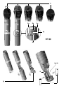
9.2. HT 80 Handheld Transmitter
9.2.1. Microphone Element
Prior to switching the transmitter on, screw the microphone element
CW onto the thread on the transmitter. All electrical connections
will be made automatically.
9.2.2. Inserting, Testing, and Removing Batteries
1. Make sure that the end of the ribbon fixed inside the battery
compartment (2f) will stick out of the battery compartment (2f).
(The ribbon is needed for removing the batteries.)
2. Push the upper end of each of the supplied batteries beneath
the fixing flange in the battery compartment (2f) from the side
and press firmly down against the battery compartment bottom.
Check that the batteries align with the polarity marks.
The transmitter will not function with the batteries inserted in-
correctly
Important: Do not try to insert the batteries straight or with the
lower end first. You would risk breaking the fixing flange so the
b a t t e ry would not be seated securely in the battery compart m e n t .
3. Set the PWR switch to “I” to switch the power to the transmitter
on.
The status LED (2b) will flash momentarily. If the batteries are in
good condition, the status LED (2b) will continue glowing dimly.
When the status LED (2b) illuminates brightly the batteries will
be dead within about 90 minutes. Replace the batteries with
new ones as soon as possible.
If the status LED (2b) fails to illuminate the batteries are dead.
Insert new batteries.
4. Screw the supplied protective ring (2j) and the battery com-
partment cover back onto the transmitter CW. You can rotate
the protective ring (2j) so that any one of the controls will be
accessible and all others covered (B to E) and thus protected
from being misadjusted unintentionally.
Note: For easy channel identification in a multichannel setup, you
can install a different-color protective ring included in the
optional Color Coding Kit. These protective rings are adjust-
able, too.
Note: If you prefer to cover all controls, reinstall the original color
code ring (2d) after adjusting the system as described
in section 9.5.
5. Removing batteries: Pull the ribbon outward to release the
batteries from the battery compartment (2f) and remove the bat-
teries.
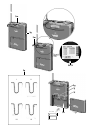
9.3. PT 80 Bodypack Transmitter
1. Insert the supplied batteries into the battery compartment (3h)
conforming to the polarity marks.
The transmitter will not function with incorrectly inserted bat-
teries.
2. Close the battery compartment (3h). The GAIN control (3j)
remains accessible through an opening in the battery compart-
ment cover.
3. Connect your microphone -- or your instrument using an option-
al MKG/L guitar cable -- to the audio input (3d).
4. Rotate the security cover (3m) CW to uncover the switches.
5. Set the POWER switch (3a) to “I” to switch the power to the
transmitter on.
The status LED (3c) will flash momentarily. If the batteries are in
good condition, the status LED (3c) will continue glowing dimly.
When the status LED (3c) illuminates brightly the batteries will
be dead within about 90 minutes. Replace the batteries with
new ones as soon as possible.
If the status LED (3c) fails to illuminate the batteries are dead.
Insert new batteries.
6. Snap the security cover (3m) back over the switches CCW.
You can wear the transmitter inside a shirt or jacket pocket, fix
it to your belt with the belt clip (3g), or attach it to your body
with adhesive bandage.
Important: Make sure the antenna will hang down freely, with-
out being covered by the body.
Note: For easy channel identification in a multichannel setup, you
can replace the snap fitted color code platelet (3e) with a dif-
ferent-color platelet included in the optional Color Coding Kit.
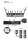
9.4. SR 80 Receiver
9.4.1. Placement
Reflections off metal parts, walls, ceilings, etc. or the shadow
effects of musicians and other people may weaken or cancel the
direct transmitter signal.
For best results, place the receiver as follows:
1. Place the receiver near the performance area (stage). Make
sure, though, that the transmitter will never get any closer to the
receiver than 16 ft. (5 m).
2. There should always be a direct line of sight between the trans-
mitter and receiver.
3. Place the receiver at least 5 ft. (1.5 m) away from any big
metal objects, wire (particularly wire mesh) or sheet metal struc-
tures, walls, scaffolding, ceilings, etc.
4. Do not place the receiver in a recess in a wall.
5. Place the receiver at least 5 ft. (1.5 m) away from any equip-
ment that may emit RF radiation such as lighting racks, fluores-
cent lamps, digital effects units, or PCs.
You can either use the receiver free-standing or mount it in a 19”
rack using the supplied RMU 80 rack mounting kit.
9.4.2. Rack Mounting
1. Slide a rack ear into the fixing rail on one side of the receiver
and the BP 80 blank panel into the fixing rail on the other side
from rear to front.
2. To mount two receivers, slide the linking section with the cover
plate pointing to the receiver front panel into the fixing rail on
one side of the receiver from rear to front. Slide the linking sec-
tion into the fixing rail on one side of the second receiver from
the rear. Slide another rack ear into the fixing rail on the other
side of the second receiver.
3. Use the supplied installation screws to fix the rack ears to the
rack. For best reception, we recommend to mount the receiv-
er(s) at the top level of the rack.
9.4.3. Audio Connection
Connect one of the AUDIO OUT sockets to the desired input:
- BALANCED socket (1o) - XLR cable - microphone input: set
BALANCED LINE/MIC switch (1p) to MIC.
- BALANCED socket (1o) - XLR cable - line input: set BALANCED
LINE/MIC switch (1p) to LINE.
- UNBALANCED jack (1n) - 1/4” jack cable - unbalanced 1/4”
microphone or line input jack. (BALANCED LINE/MIC switch
(1p) position is uncritical.)
Important: Never use the two AUDIO OUT sockets simulta-
neously! This may cause signal loss or increased noise.