


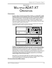

Multiple ADAT-XT Operation: Chapter 5
ADAT XT Reference Manual 61
protocol which the XT uses, and vice-versa. Refer to the User’s Manual of the digital
interface you are using for more information.
When recording digital audio into the XT from another XT or ADAT in a multiple ADAT
system, the XT recording the audio is already synchronized with the other machines,
so the digital audio is sample-locked when recorded. This is because all slave
machines are automatically set to External Clock mode (EXT icon lights in the CLOCK
icon group). However, when recording digital audio from some other source, it is
necessary to have the XT synchronize to the incoming digital audio. This can be done
differently depending on whether you are using a single XT by itself or a multiple
ADAT system.
If using a single XT, you must connect the AI-1’s ADAT OPTICAL [OUT] to the XT’s
[DIGITAL IN] using a single fiber optic connector. Press the [DIGITAL INPUT] button
on the XT, and set its Clock Source to Digital (press [CLOCK SELECT] until the DIG
icon lights in the CLOCK icon group). Now the XT will synchronize to the clock
information which accompanies the digital audio coming from the AI-1, which is
originating from the digital audio device connected to the DIGITAL [IN] of the AI-1.
In a multiple ADAT system, you have two choices: synchronize the digital audio
source to the ADAT system, or sync the ADAT system to the digital audio source.
If the source does not have any kind of clock input (i.e., it cannot be synchronized to
an external clock), you have little choice but to choose the later option. This means
you must connect the AI-1’s ADAT OPTICAL [OUT] to the [DIGITAL IN] of the master
ADAT, which of course has its [DIGITAL OUT] already connected to the next slave,
and so on. You must then set the master’s Clock Source to Digital (press [CLOCK
SELECT] until the DIG icon lights in the CLOCK icon group). If no digital audio clock
is detected (i.e. when no digital audio is being received by the AI-1), the master XT’s
DIG icon will flash and it will continue using its own internal clock. When digital audio
is sent through the AI-1 (and consequently, a digital clock is received by the master
XT), the master XT will synchronize to the incoming digital clock (the XT’s DIG clock
will stop flashing and remain lit).
If your digital audio source does provide a means for synchronizing to an external
clock, you must connect the last slave ADAT’s [SYNC OUT] to the AI-1’s [SYNC IN].
Next, you must connect the AI-1’s [WORD CLOCK OUT] connector to the digital
audio source’s [WORD CLOCK IN] connector, and adjust its
clock
parameter so that
it is synchronizing to the incoming word clock derived from the ADAT system.
DIGITAL CLOCK CONSIDERATIONS
When switching between the XT’s two internal clock sample rates (48 kHz and 44.1
kHz), the reference base used for computing tape location is changed. The result is
that the same tape location will appear to have two different time addresses
depending on the sample rate (CLOCK) you are using. Since the XT cannot detect
the sample rate of an external clock, it is therefore necessary that you select between
DIG 48K and DIG 44.1K to choose which reference base the XT should use to
calculate tape positions by while syncing to the digital clock. This is done by pressing
the [CLOCK SELECT] button. See page 44 for more information.
TAPE OFFSET
When synchronizing multiple XTs, it is possible to offset any of the slave units from
the master. The main reason for doing this would be for cut-and-paste style editing.
By bouncing audio over the digital bus to a slave machine which is offset from the
master, you can copy portions of audio to different sections of tape without having to
re-record the audio. In addition, the Tape Offset feature can be used even if the XT is
the master machine in a multiple ADAT system. This is important especially when
using the XT with one or more original ADATs as slaves.When offsetting the XT’s