


©American Audio® - www.americanaudio.us - Q-SD Instruction Manual Page 16
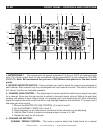
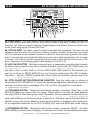
Q-SD REAR PANEL - CONTROLS AND FUNCTIONS CONT.
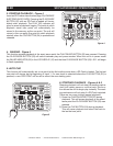
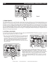
to these jacks when the LINE LEVEL SELECTOR SWITCH (55) is in the “PHONO 2” position, THIS
MAY SERIOUSLY DAMAGE YOUR MIXER! The red colored RCA jack represents the right channel
input and the white represents the left channel input. Input volume will be controlled by the channel
two fader. The channel SOURCE SELECTOR SWITCH (2) must be in the "Phono 2/Aux 2" position,
to monitor any source connected to these jacks.
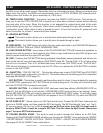
59. CHANNEL 2: LINE 2 INPUT JACKS - DO NOT CONNECT TURNTABLES TO THESE JACKS!
CD players, Tape Decks and other line level instruments may be connected to these jacks. The red
colored RCA jack represents the right channel input and the white represents the left channel input.
Input volume will be controlled by channel two fader. The channel SOURCE SELECTOR SWITCH (2)
must be in the "Line 2" position, to monitor any source connected to these jacks.
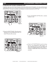
60. CHANNEL 3: AUX 3 INPUT - DO NOT CONNECT TURNTABLES TO THESE JACKS! CD players,
Tape Decks and other line level instruments may be connected to these jacks. The red colored RCA
jack represents the right channel input and the white represents the left channel input. Input volume
will be controlled by channel three fader. The channel SOURCE SELECTOR SWITCH (2) must be in
the "Aux 3" position, to monitor any source connected to these jacks.
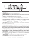
61. CHANNEL 3: LINE 3 INPUT JACKS - DO NOT CONNECT TURNTABLES TO THESE JACKS!
CD players, Tape Decks and other line level instruments may be connected to these jacks. The red
colored RCA jack represents the right channel input and the white represents the left channel input.
Input volume will be controlled by channel three fader. The channel SOURCE SELECTOR SWITCH
(2) must be in the "Line 3" position, to monitor any source connected to these jacks.
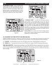
62. CHANNEL 4: RCA LINE INPUT JACKS - DO NOT CONNECT TURNTABLES TO THESE JACKS!
These Jacks are used for line level inputs. Connect CD players or Tape Decks to line level inputs.
Line level musical instruments with stereo outputs such as Rhythm Machines or Samplers should
also be connected to line level inputs. The red colored RCA jack represents the right channel input
and the white represents the left channel input. Input volume will be controlled by the channel four
fader. The channel SOURCE SELECTOR SWITCH (2) must be in the "Line 4" position, to monitor
any source connected to these jacks.
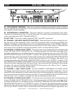
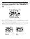
63. REC OUT - This is a low current unbalanced output source designed for various tape and CD
recorders. The Record Out (REC OUT) level is dictated by the CHANNEL FADER LEVEL (19), it is not
inuenced by the MASTER VOLUME CONTROL (5).
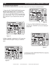
64. ZONE LEVEL OUTPUT - Use this separate output signal to drive a booth monitor or separate
sound system. The output level for these jacks will be controlled by the ZONE VOLUME KNOB
(15). These RCA jacks send a low current, unbalanced output signal. These jacks should only be
used for shorter cable runs (under 15 feet) to signal processors or looping to another mixer.
65. RCA MASTER OUTPUTS - The Master Output includes a pair XLR BALANCED JACKS (68)
as well as a pair of RCA Unbalanced Jacks. The RCA jacks send a low current unbalanced output
signal. These jacks should only be used for shorter cable runs to signal processors or looping to
another mixer. For cable runs greater than 15 feet use the XLR BALANCED JACKS (68).
66. PLAYER CONTROL CHANNELS 1 - 4 - This jack is used to control the “Q-Start” function
between the mixer and a compatible American Audio® or American DJ® CD Player. For more infor-
mation on “Q-Start” functionallity refer to the user manual included with your CD player. Be sure to
only use the mono tip mini plug included with your CD player to avoid damage to the mixer and/or
the CD player.