


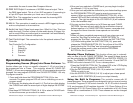
XLR MALE SOCKET
1 EARTH
HOT 2
3 COLD
XLR FEMALE SOCKET
1 EARTH
HOT 2
3 COLD
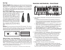
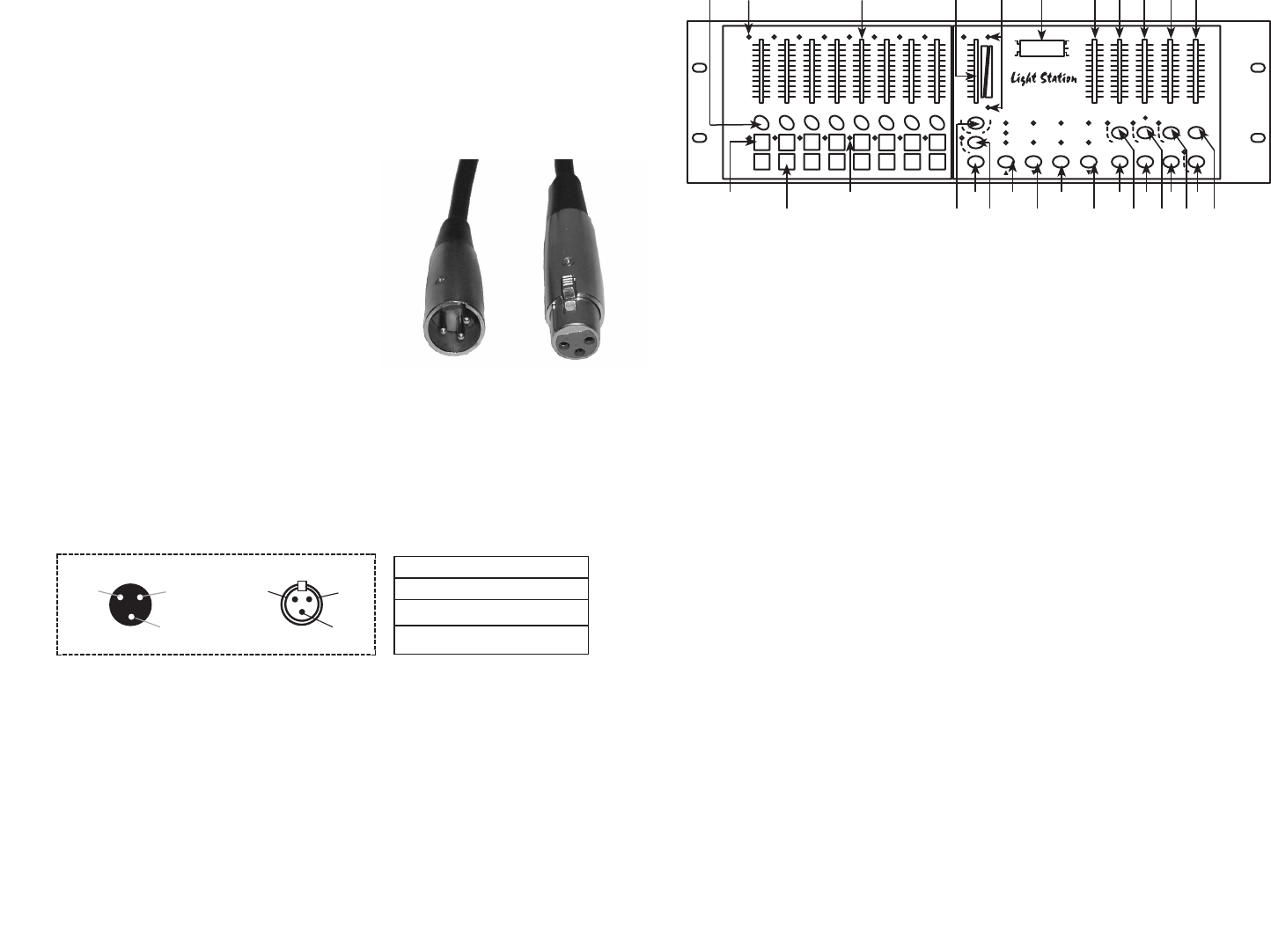
XLR Pin Configuration:
Pin 1 = Shield
Pin 2 = Data Compliment (negative)
Pin 3 = Data True (positive)
Set Up:
Power Supply: Before plugging your unit in be sure the source volt-
age in your area matches the required voltage for your American DJ®
Light Station.™ The Light Station™ is available in a 115v and 230v ver-
sion. Because line voltage may vary from venue to venue, you should be
sure to plug your power supply into a matching wall outlet before attempt-
ing to operate you controller.
Data Cable (DMX Cable) Requirements:
Your xture and your controller require a
standard 3-pin XLR connector for data
input and data output (Figure 1). If you
are making your own cables be sure to
use standard two conductor shielded cable
(This cable may be purchased at almost all
pro sound and lighting stores). Your cables
should be made with a male and female
XLR connector on either end of the cable.
Also, remember that DMX cable must be
daisy chained and can not be “Y”ed or
split.
Notice: Do not use the ground lug on the XLR connector. Do not con-
nect the cable’s shield conductor to the ground lug or allow the shield
conductor to come in contact with the XLR’s outer casing. Grounding the
shield could cause a short circuit and erratic behavior.
Special Note: Line Termination.
When longer runs of cable
are used, you may need to use a terminator on the last unit to avoid
erratic behavior. A terminator is a 90 - 120 ohm 1/4 watt resistor which is
connected between pins 2 and 3 of a male XLR connector (DATA + and
DATA -). This unit is inserted in the female XLR connector of the last unit
in your daisy chain to terminate the line. Using a cable terminator will
decrease the possibilities of erratic behavior.
Figure 1
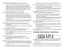
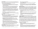
Function and Controls - Front Panel
10
0
2
4
6
8
0
2
4
6
8
10
0
2
4
6
8
10
0
2
4
6
8
10
0
2
4
6
8
10
0
2
4
6
8
10
0
2
4
6
8
10
1 2 3 4 5 6 7 8
0
2
4
6
8
10
0
2
4
6
8
10
0
2
4
6
8
10
0
2
4
6
8
10
9 10
11
12 13 14 15 16
0
2
4
6
8
10
MASTER
FADE
TIME
LEVEL AUDIO
DIMMER
SPEED
SWITCH
SPEED
FLASH 1-8
M
LATCH 9-16
FLASH 9-1 6
A
B
Cros s
Add/ Kill
Shif t
Loop Chas e Tap Sy nc Stan d By
American DJ
PATTERN STEP
Loop E xit Audio Manu al Step Manu al
Prog ram Assign Patch Full O n
End St ep Delete Program MIDI Cha nnel
Butt on Setu p Fade Time Se tup Cr oss Setu p Blin d
Assi gn Add
Assi gn Kill
Chan nel Fla sh
Fade E nabl e Cross On Enabl e
No Fad e Time Cross Of f MIDI
Sign al
Tap Sy nc
Manu al Sync
Audi o
Chas e
Manu al
®
1 2
1 3
1 4 2 4
2 3
2 2
2 1
2 0
1 9
1 8
1 7
1 6
1 5
2 6
2 7 2 9
2 8
2 5
1 6 1 11 09875432
1. Flash Buttons (Channels 1-8):These button will serve three (3)
functions:
1. In manual mode these buttons will momentarily activate any
xtures assigned to those channels. These xtures will remain on
as long as you hold down the button. Releasing the button will
switch the xtures off.
2. When used in conjunction with the ADD/KILL (17) feature, these
buttons are used to activate stored channel assignments. You
may group a number of channels to be activated at once, then
store this group in one of 16 FLASH BUTTONS (1 & 13).
3. When the BLIND feature is enabled in chase mode, pressing the
SHIFT BUTTON (16) along with a channel FLASH BUTTON will
BLIND (black out) that channel.
2 Channel Indicators (1-8): These green LEDs will glow indicating
channel activity for channels 1-8. The intensity of the LED’s will
also vary according to the channels output. Low intensity is low
channel output, while high intensity is brighter channel output.
3. Channel Faders (1-8): These faders serve two functions:
1. In manual mode, these faders will control channel output.
2. In Program mode, these faders will act as a ON/OFF switch for a
program that has been assigned to it.
4. Master Fader: This fader will serve two functions.
1. This fader will act as a master output control for the Channel
Sliders 1-8 (3) when in Manual, Chase, or Cross Function Modes.
2. When in CROSS MODE this slider is used to manually fade a
Figure 2
©American DJ Suply® www-americandj.com Light Stantion Instruction Manual Page 4©American DJ Suply® www-americandj.com Light Stantion Instruction Manual Page 3