


– 13 – AtlasSound.com
Specifications are subject to change without notice.
Owner’s Manual
ECM-RACEWY
ECM-20, ECM-20M, & ECM-30
1601 Jack McKay Blvd. • Ennis, Texas 75119 U.S.A.
Telephone: 800.876.3333 • Fax: 800.765.3435
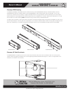
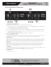
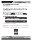
ECM-20/ECM-20M Module System Wiring Configuration
Example 1 - Single 20A AC Line
ECM wiring configuration showing one 20A AC main line coming into an ECM-20M then paralleling with five ECM-20 type modules.
Note: It appears that the wiring is in series but the ECM Module In/Out terminals are in parallel on the PCB.
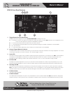
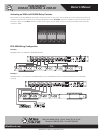
Example 2 - Dual 20A AC Line (40A)
ECM wiring configuration showing two 20A AC main line coming into the raceway for a total of 40A available. The 20A legs are
separated by feeding a 20A leg to two different ECM-20M Modules. The leg is then paralleled with two ECM-20 type modules.
Note: It appears that the wiring is in series but the ECM Module In/Out terminals are in parallel on the PCB.
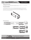
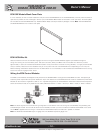
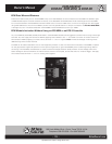
ECM Module Connection to an ECS-6RM Controller
ECS-6RM Control Ports for the ECM Modules
Up to six AC Main circuits can be activated or monitored by the ECS-6RM. Each ECM control port connects to one of the following
ECM modules: ECM-20, ECM-20M, ECM-30, ECM-15SH and ECM-20SH. For connection between the ECS-6RM and an ECM module
use a 5 conductor cable that is a minimum of 22 gauge wire. We suggest using CAT5 cable due to the common availability. Pay special
attention to the port connections and DO NOT MISS WIRE or damage may occur. The distance between the ECS-6RM and an ECM
module can be up to 1000ft.
(+) = 5VDC, G = Circuit Ground, V = AC Voltage Status Signal, A = AC Current Status Signal, D = Fault Status Signal, all signals are of
low voltage and current.
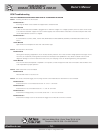
AC main
in 20A
AC main
in 20A #1
AC main
in 20A #2
Single ECM-20 Control Port