


AtlasSound.com – 16 –
Specifications are subject to change without notice.
Owner’s Manual
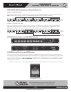
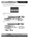
ECM-RACEWY
ECM-20, ECM-20M, & ECM-30
1601 Jack McKay Blvd. • Ennis, Texas 75119 U.S.A.
Telephone: 800.876.3333 • Fax: 800.765.3435
ECM Troubleshooting
Note: ALL TROUBLESHOOTING SHOULD BE DONE BY A CERTIFIED ELECTRICIAN
Issue 1 - Incoming AC LED is not illuminated.
Possible Cause 1
Incoming AC Mains circuit breaker has tripped due to excessive load.
Action Needed
Check the AC outlet that the ECM is plugged into for 120V AC voltage. If no voltage is present, check to see if the AC outlet
is on a GFI that has been tripped. If it has not been tripped, trace the AC Mains outlet back to the electrical panel and check
the AC Mains breaker to see if it is tripped.
Possible Cause 2
If the AC Mains is correct (120V), internal 15A (ECM-15SH) and 20A (ECM-20, ECM-20m, ECM-20SH) Slow Blow fuse is
blown.
Action Needed
Open ECM unit and replace the fuse with a Slow Blow type.
Issue 2 - AC Fault LED is illuminated.
Possible Cause
Although the Clamping Suppression circuit virtually assures protection from most transient voltage spikes and surges, nature
has a way of occasionally creating electrical forces that are beyond the capabilities of any device to absorb without some
degree of damage. In the rare instance that this occurs, the clamping circuit can be damaged during the suppression.
Action Needed
The unit will need to be repaired or replaced. It is important to have all equipment that was connected to that AC Mains Line
to be inspected for proper operation.
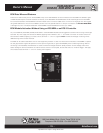
Issue 3 - ECM Active LED is not illuminated.
Possible Cause
Manual slide switch is not set to On.
Issue 4 - Unit is set to External Trigger, the Incoming AC LED is illuminated but the Active LED is not illuminated.
Possible Cause 1
External Switch is not connected across the “D” and “+” terminals.
Possible Cause 2
External DCV is not connected across the “+” and “G” terminals.
Possible Cause 3
External DCV voltage polarity is not correct across the “+” and “G” terminals.
Possible Cause 4
External DCV voltage is too low to activate the trigger circuit. Must be a minimum of 5vDC.