


Adjusting ”Off” Attenuation
In instances when the number of microphones in use is high, it may be necessary to increase
the amount of “off” attenuation per microphone to keep the total ambient noise level low.
There are “off” attenuation adjustments inside the unit. To adjust the “off” attenuation of
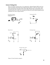
channel 1, unplug the unit, remove the top cover and locate the trimpot designated on the
circuit board by “VR3” (Figs. 4 and 5, page 11). It is factory set at approximately 8 dB, the
attenuation at the middle of the control’s rotation. When the control is turned fully counter-
clockwise, “off” attenuation is approximately 20 dB. Conversely, when the adjustment is
turned fully clockwise, “off” attenuation is approximately 6 dB. VR6, VR9 and VR12 control
“off” attenuation for channels 2, 3 and 4 respectively.
Changing the settings of the switches designated on the circuit board by “SW5,” “SW11,”
“SW17” and SW23” will extend the range of “off” attenuation to –40 dB for channels 1, 2, 3
and 4 respectively.
Preamp Outputs
Each microphone channel has an independent unbalanced preamp output that is separate
from the main mixer output. This is helpful when it is necessary to record the output of each
channel, whether or not it is the active mixer output (as is required, for example, in some
courtroom proceedings). As set at the factory, no gating is applied to these outputs. To gate
these outputs, unplug the unit, remove the top cover and locate the switches designated on
the circuit board by “SW6,” “SW12,” “SW18” and SW24” (Figs. 4 and 5, page 11). Change the
switch position(s) to “Gating” for channels 1, 2, 3 and/or 4 respectively, as desired.
Input Limiters
Independent, adjustable limiters are available on all mic channels. To adjust the limiter
threshold of channel 1, unplug the unit, remove the top cover and locate the trimpot designated
on the circuit board by “VR2” (Figs. 4 and 5, page 11). It is factory set at approximately 0 dB
RMS. When the control is turned fully counter-clockwise, limiter threshold is approximately
–10 dB RMS. Conversely, when the adjustment is turned fully clockwise, limiter threshold
is approximately +10 dB RMS. VR5, VR8 and VR11 adjust limiter threshold for channels 2, 3
and 4 respectively.
Changing the settings of the switches designated on the circuit board by “SW4,” “SW10,”
“SW16” and SW22” will turn off the threshold-limiting function on channels 1, 2, 3 and 4
respectively.
Force-on/Force-off
To activate force-on/force-off, install a closure between the appropriate pin and Ground
Reference on the External Control connector on back of unit.
12
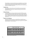
External Control Connector Pinout
Pin 1 Channel 1 force off Pin 8 Channel 4 force on
Pin 2 Channel 2 force off Pin 9 Channel 1 TTL out
Pin 3 Channel 3 force off Pin 10 Channel 2 TTL out
Pin 4 Channel 4 force off Pin 13 Ground reference
Pin 5 Channel 1 force on Pin 14 Channel 3 TTL out
Pin 6 Channel 2 force on Pin 15 Channel 4 TTL out
Pin 7 Channel 3 force on