


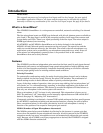
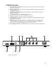
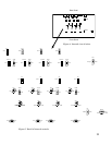
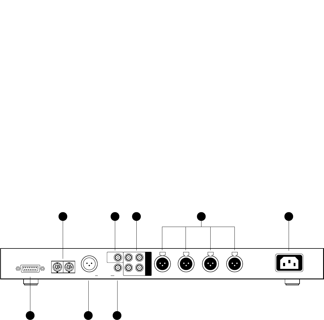
AT-MX351 Rear Panel
1. External Control connector. For TTL output, plus closure-control input for external
control of each channel.
2. Link In/Link Out. Provides for daisy-chaining of multiple mixers when more than four
microphones are used.
3. Line/Mic balanced output. Level can be changed via internal switch (see page 10).
XLRM-type connector.
4. Unbalanced line-level (–10 dBV) output. RCA jack.
5. Aux In. Unbalanced, line-level (–10 dBV), auxiliary input.
6. Preamp Outputs. Independent, unbalanced (–10 dBV), switchable pre/post-controller
outputs from mic channels.
7. Inputs. Balanced microphone inputs for low-impedance dynamic or condenser mics.
Can be changed to line-level inputs via internal switches (see page 10). XLRF-type
connectors. Can supply 48V phantom power via internal switches.
8. Power input. 120V/230V AC, 50/60 Hz. Select input voltage via switch on bottom panel.
Figure 2. Rear panel
7
External Control
AC In
Link Out
Input 4
Line/Mic
0/-50
Input 3 Input 2 Input 1
Outputs
-10
Link In
Channel
31
42
Pre-
amp
out
Aux
in
-10
431
8652 7