


The preamplifier gain may be reduced further, allowing the SmartMixer to accept line-level
sources. Changing the settings of the internal switches designated by “SW3,” “SW9,” “SW15”
and “SW21” will cause an input reduction of 50 dB for channels 1, 2, 3 and 4 respectively.
Note that the appropriate internal switches can be used in combination for a total sensitivity
reduction of up to 60 dB for each channel.
Output Level
The SmartMixer’s output is factory set at line level. Should mic-level output be desired,
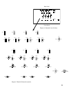
simply unplug the unit, remove the top cover and locate the switch on the circuit board
marked “SW26” (Figs. 4 and 5, page 11). Changing the setting of this switch will cause a
50 dB reduction in output.
Phantom Power
Each of the SmartMixer’s inputs supplies +48V DC phantom power. Should it be required
to disable the phantom power, simply unplug the unit, remove the top cover and locate the
switches designated on the circuit board by “SW1,” “SW7,” “SW13” and “SW19” (Figs. 4 and 5,
page 11). Changing the settings of these switches will disable phantom power on channels 1,
2, 3 and 4, respectively. Note that, although they do not require phantom power for operation,
most balanced-output dynamic microphones can be used without disabling the SmartMixer’s
phantom power.
Output Level LED Meter
The Output Level LED meter is factory set to indicate RMS output. Should peak output
indication be desired, simply unplug the unit, remove the top cover and change the setting of
the switch designated on the circuit board by “SW27” (Figs. 4 and 5, page 11). “Zero” (0) level
is factory-calibrated at +4 dBm into 600 ohms.
10
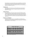
Summary of Internal Controls
Function Ch 1 Ch 2 Ch 3 Ch 4 Output
48V Phantom Power SW1 SW7 SW13 SW19
10 dB Input Atten. SW2 SW8 SW14 SW20
50 dB Mic/Line Atten. SW3 SW9 SW15 SW21 SW26
Limiters (on/off) SW4 SW10 SW16 SW22
“Off” Atten. Range SW5 SW11 SW17 SW23
Preamp Output Gating SW6 SW12 SW18 SW24
Limiter Thresholds VR2 VR5 VR8 VR11
“Off” Atten. Adjustment VR3 VR6 VR9 VR12
NOMA -- -- -- -- SW25
Meter RMS/Peak -- -- -- -- SW27
Figure 3. Summary of internal controls