


CV
G
R
Driving One LED
I
≈
2v
R+40Ω
Driving Lamps
2N3904
+
CV
10
KΩ
G
G
CV
Driving Logic Gates
Equivalent Output
Circuit for Control
Voltage Out
CONTROL
VOLTAGE
40Ω
GND
Relay Driver
2N3904
IN4001
+
CV
10KΩ
RELAY
COIL
G
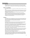
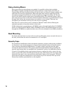
Control Voltage Out
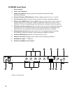
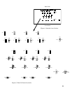
When a microphone channel turns “on,” as indicated by a Selected Channel LED on the front
panel, the channel’s associated Control Voltage Out goes “high” (+4 VDC). See chart on page
12 for pin connection. This signal can be used to light indicator lamps, switch speaker zones
on and off, select video cameras, etc. The control voltage should not be connected directly to an
inductive load such as a relay coil, as damage to the mixer may result. Several interface circuit
possibilities are shown in Figure 6 below.
Figure 6. Control interface examples.
13
CV
G
R
Driving One LED
I
≈
2v
R+40Ω