


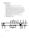
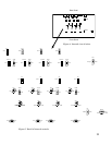

AT-MX351 Front Panel
1. Power switch.
2. Power “on” indicator.
3. Input Gain controls. Adjust inputs for microphone sensitivities and/or
operating conditions.
4. Selected Channel LED indicators. Indicate which channels are “on” or “active.”
5. Aux In control. Adjusts input for source output level and/or operating conditions.
6. Output Level LED meter. Indicates RMS output level of the mixer. “Zero” (0) level is
factory calibrated for an output of +4 dBm into 600 ohms (Master level control fully
clockwise). Can be set for peak output level indication via internal switch (see page 10).
7. Priority Pre-select switches (1-4). A switch in the “up” position assigns the respective
channel priority over the other channels. A priority channel can not be locked out by
other channels. Any combination of priority/non-priority selections is allowed.
8. Manual mode switch. Setting this switch in the “up” position bypasses all of the
SmartMixer’s automatic functions, except limiting and NOMA if selected.
9. Lockout LED indicator. Shows when lockout bus is active.
10. Master level control. Adjusts mixer output level for operating conditions.
11. Headphone output.
1
/
4
” TRS jack.
12. Monitor headphone level control.
Figure 1. Front panel
Gain 1 Gain 2 Gain 3Gain 4Aux In
AUTOMATIC MIXER
AT-MX351
Power
Selected Channel
Output Level
Priority Pre-select
1
2
3
4
Master
Lockout
-20
-10 -6
-3
0
+3
+6
Manual
Monitor
6
12
11987421
10653