


Pro Series 5 Installation and Operation
2
This device complies with part 15 of the FCC Rules. Operation is subject
to the condition that this device does not cause harmful interference.
This device complies with INDUSTRY CANADA R.S.S. 210, en conformité
avec IC: RSS-210/CNR210. Operation issubject to the following
conditions: 1) This device may not cause harmful interference and 2) this
device must accept any interference received, including interference
which may cause undesired operation. Changes or modications not
expressly approved by Audio-Technica could void your authority to
operate this equipment.
CAUTION! Electrical shock can result from removal of the receiver
cover. Refer servicing to qualied service personnel. No user-
serviceable parts inside. Do not expose to rain or moisture.
The circuits inside the receiver and transmitter have been precisely
adjusted for optimum performance and compliance with federal
regulations. Do not attempt to open the receiver or transmitter. To do so
will void the warranty, and may cause improper operation.
Notice to individuals with implanted cardiac pacemakers or
AICD devices:
Any source of RF (radio frequency) energy may interfere with normal
functioning of the implanted device. All wireless microphones have
low-power transmitters (less than 0.05 watts output) which are unlikely
to cause difculty, especially if they are at least a few inches away.
However, since a “body-pack” mic transmitter typically is placed against
the body, we suggest attaching it at the belt, rather than in a shirt
pocket where it may be immediately adjacent to the medical device.
Note also that any medical-device disruption will cease when the RF
transmitting source is turned off. Please contact your physician or
medical-device provider if you have any questions, or experience any
problems with the use of this or any other RF equipment.
Thank you for choosing an Audio-Technica professional wireless
system. You have joined thousands of other satised customers who
have chosen our products because of their quality, performance and
reliability. This Audio-Technica wireless microphone system is the
successful result of years of design and manufacturing experience.
Each Pro Series 5 wireless system provides a choice of eight PLL
synthesized UHF frequencies in the 542-561 MHz band (TV channels
26-29). All Pro Series 5 wireless systems offer both manual and
automatic frequency scanning. Each wireless system includes a
receiver and either a body-pack or handheld transmitter. Individual
components are also available separately.
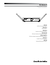
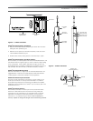
The PRO-R500 receiver features Diversity Reception. Logic circuitry
monitors reception, selecting the superior signal from two antennas,
providing better sound quality and reducing the possibility of
interference and dropouts. Soft-touch controls provide convenient
access to selection of operating frequency and automatic scanning,
while an LED display indicates selected channel and scanning
operation.
The versatile PRO-T501 UniPak
®
body-pack transmitter has both
low- and high-impedance inputs plus a bias connection, for use
with dynamic and electret condenser microphones, as well as Hi-Z
instrument pickups. The UniPak
®
transmitter also offers separate trim
controls for guitar and microphone, plus switchable high/low RF power.
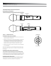
The PRO-T502 handheld dynamic microphone/transmitter features a
rugged dynamic unidirectional element designed for professional live-
sound venues.
Transmitters in the Pro Series 5 use two 1.5V AA batteries for
economical operation and wide availability. Both transmitters also
feature a multi-color Power/Mute/Battery indicator.
Pro Series 5 receivers feature a sophisticated Tone Lock
™
tone squelch
system that opens the receiver’s audio output only when a Pro Series
5 transmitter is detected, reducing the possibility of interference. As a
result, Pro Series 5 transmitters and receivers must be used together
and should not be used with components from other Audio-Technica
wireless systems, or with those of other manufacturers.
Please note that in multiple-system applications there must be a
transmitter-receiver combination set to a separate channel (frequency)
for each input desired (only one transmitter for each receiver).
Because the wireless frequencies are within UHF TV frequency bands,
only certain channels (operating frequencies) may be useable in a
particular geographic area. The eight channels (operating frequencies)
that are used in the Pro Series 5 have been selected for multi-channel
compatibility. Subject to frequency availability in a particular geographic
area, any of these eight channels may be used together.
The operating frequencies that correspond to each of the eight
channels are listed on page 7.
Receiver Installation
Location
For best operation the receiver should be at least 3' (1 m) above the
ground and at least 3' (1 m) away from a wall or metal surface to
minimize reections. Keep the receiver antennas away from noise
sources such as digital equipment, motors, automobiles and neon
lights, as well as away from large metal objects. In multi-channel
systems, position receivers at least 3' (1 m) apart and keep operating
transmitters at least 6' (2 m) from the receivers to help assure
maximum RF performance.
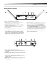
Output Connection
There are two audio outputs on the back panel: balanced (-16.5 dBV)
and unbalanced (-13.5 dBV). Use shielded audio cable for the connection
between the receiver and the mixer. If the input of the mixer is a
1
/
4
" jack,
connect a cable from the
1
/
4
" unbalanced audio output on the back of the
receiver housing to the mixer. If the input of the mixer is an XLR-type
input, connect a cable from the balanced XLR-type audio output on the
back panel to the mixer.
Power Connection
Connect the DC plug on the included AC power adapter to the DC
power input on the back of the receiver. Secure the cord over the cord
hook on the back of the receiver, to keep the plug from being detached
by an accidental tug on the cord. Then plug the adapter into a standard
120 Volt 60 Hz AC power outlet.
Antennas
Extend the permanently attached UHF antennas. The antennas are
normally positioned in the shape of a “V” (both 45° from vertical) for
best reception. Diversity Indicators on the receiver front panel will
indicate which antenna is active.