


Pro Series 5 Installation and Operation
6
System Operation
Plug in the receiver.
Receiver on...
The LED display will light up. If either A or B diversity indicators lights
up at this point (without transmitter on) there may be interference in
the area. If this occurs, change the operating channel.
How to Make Operating Channel Changes
Operating channel changes (frequency changes) may be made in two
ways: manually and automatically.
• To change channel manually
Press the Select button repeatedly until desired channel is reached.
Press and hold the Set/Scan button to manually set the receiver to
indicated channel. Channel number will stop ashing. (A brief touch
of the Set/Scan button will revert to previously set channel). If the Set/
Scan button is not pressed within 10 seconds to conrm the selection,
the system will revert to its original channel.
• To change channel automatically
Press and hold the Set/Scan button for about two seconds. The
current channel will ash three times quickly; then the system will
begin to scan for the next open channel. When it nds an open
channel, it will ash the open channel three times and then set the
channel. (If an open channel is not found, the automatic scan will
return to the original channel and ash 5 times.)
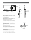
Transmitter On…
Before turning on the transmitter, use the provided screwdriver to set
the transmitter channel selector switches (Fig. C on page 4 and Fig. D
on page 5) to the same number that is displayed on the receiver. Select
channels 1-8 (channels 9 and 0 are for service use). The transmitter
may be either on or off when changing channels (frequencies). When
changing channels with the transmitter on and unmuted, the LED will
turn red as the adjustment is being made; it will turn green when the
channel is set. (When changing channels with the transmitter on and
muted, the LED will remain red during and after channel adjustment, as
long as the transmitter is muted; when the transmitter is unmuted, the
LED will turn green.)
The transmitters have a soft-touch Power/Mute button. When the
transmitter is “on,” the transmitter produces both RF and audio.
When the transmitter is switched on and in normal operation, the
receiver’s diversity indicators will display which antenna is active.
Setting Levels
Correct adjustment of transmitter audio input, receiver audio output,
and mixer/amplier input and output levels is important for optimum
system performance.
CAUTION! The small trimmer controls are delicate; use only the
supplied screwdriver. Do not force the trimmers beyond their normal
190° range of rotation.
Return the screwdriver to its storage clip when not in use.
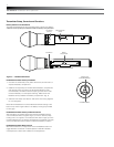
PRO-T502 Handheld Transmitter
The Pro Series 5 handheld transmitter trim (volume) control (Fig. C on
page 4) has factory pre-set audio input levels. Factory setting is full
clockwise, maximum gain.
Set the receiver’s AF Level control to its full clockwise position
(maximum). (Fig. B on page 3).
While speaking/singing into the microphone at typically loud levels,
check the AF peak indicator on the receiver. If the AF peak indicator is
easily illuminated and distortion is heard through the system, it may be
necessary to adjust the transmitter audio input level.
To adjust the transmitter audio input level, unscrew the lower body
cover and slide it downwards, exposing the screwdriver and trim control
(Fig. C on page 4). Remove the screwdriver and gently turn the trim
control counterclockwise until the AF peak indicator is illuminated only
on audio peaks.
Return the screwdriver to its clip and close and secure the lower body.
No further transmitter gain adjustments should be needed, as long as
the acoustic input does not change signicantly.
PRO-T501 UniPak
®
Transmitter
Trim controls in the UniPak transmitter (Fig. D on page 5) will enable
you to use microphones or instruments with different output levels.
1. For MIC: Set MIC (microphone trim) control fully clockwise
(maximum) and INST (instrument trim) control fully counter
clockwise (low).
For INSTRUMENT: Set INST (instrument trim) control fully
clockwise (maximum) and MIC (microphone trim) control fully
counterclockwise (low).
2. Set the receiver’s AF Level control to its full clockwise position
(maximum). (Fig. B on page 3).
3. Plug the mic or instrument into the transmitter and power up
the system.
4. For MIC: Make an initial adjustment of the mixer’s level controls that
will allow audio through the system.
For INSTRUMENT: Make an initial adjustment of the instrument
amplier input level control that will allow audio through the system.
5. For MIC: While speaking/singing into the microphone at typically
loud levels, check the AF peak indicator on the receiver. If AF peak
indicator is easily illuminated and distortion is heard through the
system, it may be necessary to adjust the transmitter audio input
level. To adjust the transmitter audio input level, gently turn the
microphone trim control counterclockwise until the AF peak
indicator is illuminated only on audio peaks.
For INSTRUMENT: While playing the instrument at typically loud
levels, check the AF peak indicator on the receiver. If AF peak
indicator is easily illuminated and distortion is heard through the
system, it may be necessary to adjust the transmitter audio input
level. To adjust the transmitter audio input level, gently turn the
instrument trim control counterclockwise until the AF peak indicator
is illuminated only on audio peaks.