


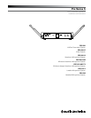
Pro Series 5 Installation and Operation
3
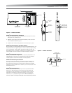
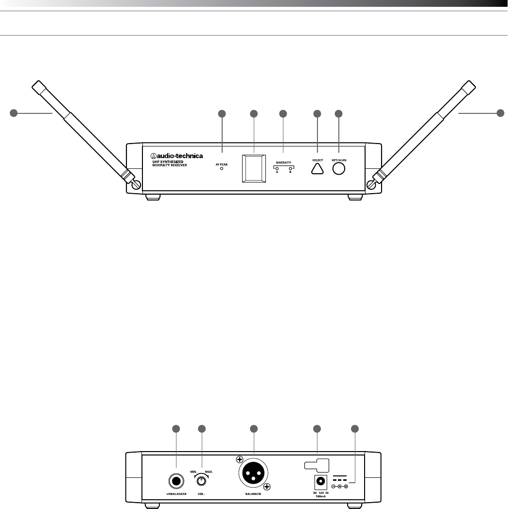
Receiver Controls and Functions
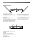
Figure A — Front Panel Controls and Functions
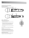
1. ANTENNAS: Position the antennas as shown in Figure A Fully
extend both antennas by pulling on the endcaps.
2. AF PEAK INDICATOR: Indicates when maximum transmitter
modulation without distortion has been reached. Not affected by
position of Volume control (Fig. B).
3. LED WINDOW: LED Display indicates channel setting and
scanning operation.
4. DIVERSITY INDICATORS: Indicates which antenna (A or B) has
better reception and is in operation.
5. SELECT BUTTON (for manual channel selection): Press the Select
button repeatedly until desired channel is reached. Press and hold
the Set/Scan button to manually set the receiver to indicated
channel. Channel number will stop ashing. (A brief touch of the
Set/Scan button will revert to previously set channel). If the Set
button is not pressed within 10 seconds to conrm the selection,
the system will revert to its original channel.
1 1
2 4 5 6
3
1 2 43 5
6. SET/SCAN BUTTON: The Set/Scan button can be used in two
ways: 1) in conjunction with the Select button to permit manual
selection of an operating channel in Manual Set Mode (see
“Select button” description above); and 2) Automatic Scan/Set
Mode, to initiate the automatic channel scan and selection, as
follows: Automatic Scan/Set Mode: Press and hold the Set/Scan
button for about two seconds. The current channel will ash three
times quickly; then the system will begin to scan for the next
open channel. When it nds an open channel, it will ash the
open channel three times and then set the channel. (If an open
channel is not found, the automatic scan will return to the
original channel and ash 5 times.)
Figure B — Rear Panel Controls and Functions
1. UNBALANCED AUDIO OUTPUT JACK:
1
/
4
" phone jack. Can be
connected to an unbalanced aux-level input of a mixer, guitar amp or
tape recorder.
2. AF LEVEL (VOLUME) CONTROL: Adjusts audio output level of both
AF Output jacks; maximum output is fully clockwise.
3. BALANCED AUDIO OUTPUT JACK: XLRM-type connector. A
standard 2-conductor shielded cable can be used to connect the
receiver output to a balanced microphone-level input on a mixer or
integrated amplier.
4. CORD HOOK: Loop the cord around the cord hook to keep the DC
plug from pulling out accidentally.
5. POWER INPUT JACK: Connect the DC plug from the included
in-line AC adapter.