


21
MH10 c
oNFigurAtioNs
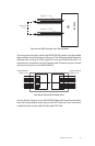
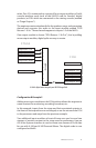
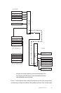
mixer. Port 10 is connected to a group of four output modules or Pro64
console interface cards (such as the 6416Y2 card for Yamaha® digital
products) at FOH which are connected to the mixing console (marked
as “Stage Outputs”).
The engineer creates mixed audio for the speakers, amps, and processing
devices and connects this audio to the input module marked “FOH
Returns 1-16 In.” These channels appear at outputs 1-9 of the MH10.
One output module is shown (“FOH Returns 1-16 Out”), but by adding
more output modules, digital splits are easy to create.
MH10
1
2
3
4
5
6
7
8
9
10
Stage Inputs 1-16
Stage Inputs 17-32
Stage Inputs 33-48
Stage Inputs 49-64
Stage Outputs 1-16
FOH Returns 1-16 Out
FOH Returns 1-16 In
Stage Outputs 17-32
Stage Outputs 33-48
Stage Outputs 49-64
STAGE
FOH
A 64x16 digital snake using only one MH10 Merger Hub
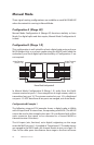
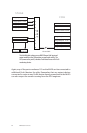
Configuration B Example 2
Adding more input modules at the FOH position allows the engineer to
create content for monitoring, recording, broadcast, etc.
In this example, inputs from the stage and their associated outputs at
the front-of-house position are unchanged, as are the returns from FOH
to the processors and amps from the previous example.
Two additional input modules at front-of-house are used to send two
streams of monitor content to the stage area for performers. Here an
ASI A-Net Systems Interface is used to create two streams of Pro16 data
for use with A-16II and A-16R Personal Mixers. The digital snake is now
configured as 64x48.