


24
MH10 c
oNFigurAtioNs
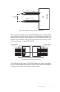
A-Net Receive
(Ports 1-10)
A-Net Transmit
(Ports 1-10)
A-Net Receive
(Ports 1-10)
A-Net Transmit
(Ports 1-10)
A-Net Receive
(Ports 1-10)
A-Net Transmit
(Ports 1-10)
1
2
3
4
5
6
7
8
9
10
1
2
3
4
5
6
7
8
9
10
Merger Distributor
1
2
3
4
5
6
7
8
9
10
1
2
3
4
5
6
7
8
9
10
Merger Distributor
1
2
3
4
5
6
7
8
9
10
1
2
3
4
5
6
7
8
9
10
Merger Distributor
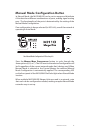
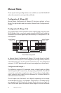
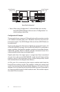
Manual Mode Conguration C
P Note: When using Configuration C in Manual Mode, be sure that
both MH10/MH10f Merger Hubs are set to Configuration C to
avoid creating a data loop.
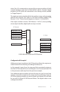
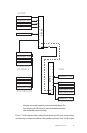
Configuration C Example
This example shows a stage-to-FOH application with a monitor console,
a 64-channel recording split, and a broadcast feed from the front-of-
house mix outputs. Two MH10 Merger Hubs are shown; MH10f hubs can
be substituted.
Inputs on the stage (mic, line-level, or digital) are connected to ports 1-8
of the MH10/MH10f on stage. Port 8 on this MH10/MH10f is connected to
output modules that feed the monitor console and recording devices.
(Optionally, another MH10 or MH10f could be connected to port 8 to
create a parallel rather than serial digital split.)
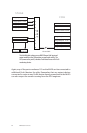
Digital audio from the stage inputs is merged and then transmitted
via port 10 to the second MH10/MH10f at the front-of-house mixing
position. (Port 9 is the redundant Cat-5e or fiber backup cable, shown
with a dotted line in the diagram that follows.)
At FOH, port 10 is connected to four output modules which feed the
front-of-house mixing console. The engineer creates mix content and
sends it into an input module (marked as “Returns 1-16”) at port 5 in the
diagram. Port 8 on the front-of-house MH10/MH10f is also connected to
an output module located in the broadcast area. This module outputs
the same FOH mix content.