


23
MH10 c
oNFigurAtioNs
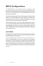
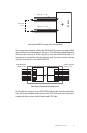
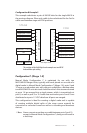
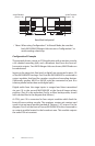
Configuration B Example 3
This example substitutes a pair of MH10f hubs for the single MH10 in
the previous diagram. Fiber optic cable is also substituted for the Cat-5e
cable used between stage and FOH positions.
MH10f
1
2
3
4
5
6
7
8
9
10
MH10f
1
2
3
4
5
6
7
8
9
10
Stage Inputs 1-16
Stage Inputs 17-32
Stage Inputs 33-48
Stage Inputs 49-64
Stage Outputs 1-16
FOH Returns 1-16 Out
Pro16
Monitors 1
Pro16
Monitors 2
FOH Returns 1-16 In
Stage Outputs 17-32
Stage Outputs 33-48
Monitor Sends 17-32
Monitor Sends 33-48
Stage Outputs 49-64
ASI
Fiber Optic Cable
STAGE
FOH
This variation of the 64x48 digital snake example uses two MH10f
hubs and ber optic cabling.
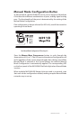
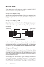
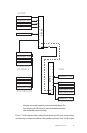
Configuration C (Merge 1-8)
Manual Mode Configuration C is optimized for use with two
MH10/MH10f Merger Hubs, typically with each placed on one side of a
digital snake. In Manual Mode Configuration C (Merge 1-8), ports 9 and
10 serve as a redundant pair, with one port available as a backup when
two MH10/MH10f units are used. Audio from the A-Net streams received
at ports 1-8 are merged into a single stream, which is transmitted out
port 8, as well as port 9 or 10. Audio data received at ports 9 and 10 are
distributed out ports 1-7. VDC data from all ports are merged.
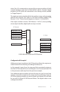
This configuration is ideal for creating a digital snake and is capable
of creating multiple digital splits of the stage source material for
connection to a monitor console as well as to recording and broadcast
devices.
P Note: Never connect more than one cable between ports 9 and 10
except in Manual Mode Configuration C; doing so will result in
a data loop.