


en
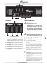
Control elements
6
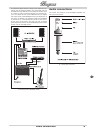
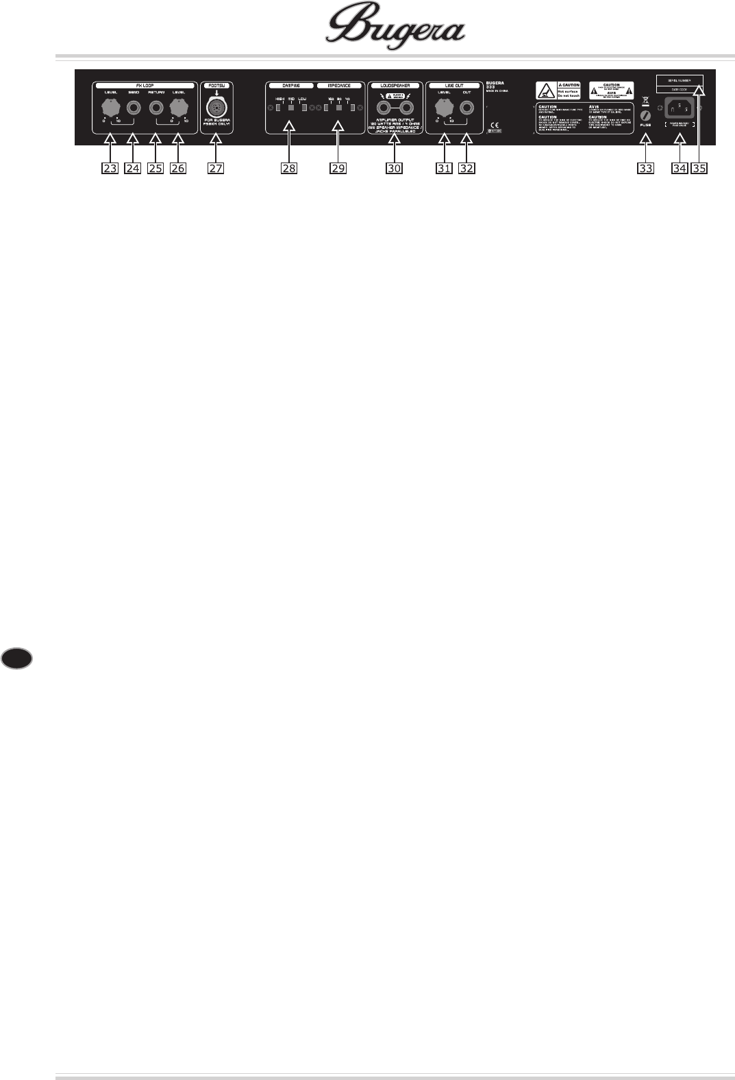
Rear panel
CAUTION!
!
Hot! Risk of injury! During use, the valves
get very hot and high surface temperatures
may be reached at the rear of this unit.
Avoid touching the controls and connectors
on the rear panel during use. To avoid acci-
dental contact with hot surfaces, place the
rear panel so that it faces a wall.
The calibrated 23 LEVEL control determines the signal
level sent to an external effects unit or any other
signal processor (0 – 10). Turn the control to the
right to increase the amount of signal information,
and turn it to the left to decrease the amount. It
makes sense to select a high setting in order to
get a possibly noise-free signal. The FX Send Level
and FX Return Level (26) controls should always be
set oppositely. For example, to reach a 0 dB work-
ing level when the FX Send Level is set low, the FX
Return Level (26) needs to be set high accordingly.
On the other hand, if you wish to boost the volume
level, turn both controls to a higher setting.
The 24 SEND output is used to connect a shielded ¼"
mono jack cable to the input of an external effects
unit.
The 25 RETURN input is used to connect a shielded
¼" mono jack cable to the output of an external
effects unit.
The calibrated 26 LEVEL control determines the signal
level returned from an external effects unit or any
other signal processor (0 – 10). Turn the control
to the right to increase the amount of signal in-
formation, and turn it to the left to decrease the
amount. To achieve a possibly noise-free signal, set
the FX Send Level (23) relatively high and the FX
Return Level relatively low. A BOOST effect can be
achieved with this LEVEL control when the RETURN
input isn’t being used. Increase the volume level
with this control plus activate the FX LOOP with the
footswitch in order to make the guitar signal louder.
This function is great for highlighting solos.
The 7-pin 27 FOOTSW(itch) connector is provided
to connect to the supplied BUGERA FSB104 foot-
switch. Please be sure to connect the cables before
switching on the amplier. Refer to „Footswitch“ for
details.
The 28 DAMPING switch lets you specify the damping
factor of the BUGERA (only 333 and 333-212). The
term „damping“ refers to a feature of the ampli-
er that affects the signal’s fade-out phase. A high
damping factor (HIGH) makes the signal fade out
quicker than a low factor (LOW). Changes to the
damping factor automatically result in level altera-
tions which should be re-adjusted.
The 29 IMPEDANCE switch lets you specify the loud-
speaker impedance. Always apply the value that
is identical to the impedance of the used speaker
cabinet. When connecting two cabinets with the
same impedance, the switch should be set to half
the value of one of the cabinets. For example, two
16-Ohm cabinets would require an 8-Ohm setting,
while two 8-Ohm cabinets need to be set to the
minimum impedance of 4 Ohms. Please also read
„Wiring the BUGERA“.
!
Both the paralleled 30 LOUDSPEAKER outputs (¼"
mono jacks) are used to connect the speaker
cabinet(s). The minimum impedance is 4 Ohms. The
IMPEDANCE switch should always be set to match
the impedance of the used speaker cabinet.
ATTENTION! TO AVOID DAMAGE TO YOUR
!
AMP, NEVER USE THE BUGERA VALVE AM-
PLIFIER WITHOUT A LOUDSPEAKER CON-
NECTED!
This is the 31 LEVEL control that species the signal
level for the OUT (32) in order to adjust the level
of a second amplier and loudspeaker system con-
nected over the OUT to the LOUDSPEAKER outputs
(30) of one or more connected speaker cabinets.
The 32 OUT provides a preamp signal in order to feed
the signal to a second amplier and loudspeaker
system, for example.
*
WARNING: ONLY REPLACE THE FUSE WHEN THE 33
MAINS CABLE HAS BEEN DISCONNECTED! The
FUSE is found in the fuse holder. If the fuse is
blown, it needs to be replaced with a fuse of the
same kind by all means. Otherwise, the unit could
seriously be damaged, in which case the warranty
is void. If the fuse is blown repeatedly, you should
take the unit to a qualied service technician.
*
The 34 IEC MAINS connector is used to connect the
mains cable that has the appropriate voltage rat-
ings for your country (included). At all times, make
the connections to the amplier before plugging the
cable into a power outlet.
This is the 35 SERIAL NUMBER of the amplier.
Rear panel of the BUGERA 333