


4
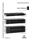
ULTRAGRAPH PRO FBQ1502/ULTRAGRAPH PRO FBQ3102/ULTRAGRAPH PRO FBQ6200
The FBQ1502 requires just one rack space, yet it offers you
tons of effective methods for adjusting the sound characteristics,
and is ultra-compact and extremely simple to operate.
The FBQ3102 features 31 frequency bands per channel as
well as adjustable high-pass and low-pass filters. These filters
further augment the adjustability options available to you.
With its integrated limiters, noise generator and the adjustable
subwoofer output with signal level display and its 62 lighted
45 mm faders, the FBQ6200 is our top model in this category.
Future-oriented BEHRINGER technology
To assure the highest possible degree of usability, all our
equipment is manufactured adhering to the highest quality
standards in the audio industry. Your equalizer has been
manufactured under ISO9000 certified management system.
Relay-controlled hard bypass
The so-called hard bypass relays were integrated into the
development concept of the FBQ6200 and the FBQ3102. These
relays assure that your equalizer is automatically switched into
bypass mode in the event of loss of power or faulty power
delivery. These fail-safe relays also produce a slight delay during
powering up in order to avoid dangerous switch-on thumps.
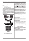
Balanced inputs and outputs
The BEHRINGER ULTRAGRAPH PRO models feature electronic
servo-balanced inputs and outputs. The servo function performs
automatically, recognizing when unbalanced signals are
connected and internally converts the nominal signal level so
that no signal level difference between input and output signals
occurs (6 dB correction).
+ The following users manual is intended to
familiarize you with the units control elements, so
that you can master all the functions. After having
thoroughly read the users manual, store it at a safe
place for future reference.
1.1 Before you get started
1.1.1 Shipment
The ULTRAGRAPH PRO was carefully packed at the factory
to assure secure transport. Should the condition of the cardboard
box suggest that damage may have taken place, please inspect
the unit immediately and look for physical indications of damage.
+ Damaged units should NEVER be sent directly to us.
Please inform the dealer from whom you acquired
the unit immediately as well as the transportation
company from which you took delivery of the unit.
Otherwise, all claims for replacement/repair may
be rendered invalid.
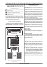
1.1.2 Initial operation
Please make sure the unit is provided with sufficient ventilation,
and never place the ULTRAGRAPH PRO on top of an amplifier or
in the vicinity of a heater to avoid the risk of overheating.
+ Before plugging the unit into a power socket, please
make sure you have selected the correct voltage:
The fuse compartment near the power plug socket contains
three triangular markings. Two of these triangles are opposite
one another. The voltage indicated adjacent to these markings is
the voltage to which your unit has been set up, and can be
altered by rotating the fuse compartment by 180°. ATTENTION:
This does not apply to export models that were for
example manufactured only for use with 120 V!
+ If you alter the units voltage, you must change the
fuse accordingly. The correct value of the fuse
needed can be found in the chapter
SPECIFICATIONS.
+ Faulty fuses must be replaced with fuses of
appropriate rating without exception! The correct
value of the fuse needed can be found in the chapter
SPECIFICATIONS.
Power is delivered via the cable provided with the unit. All
requiered safety precautions have been adhered to.
+ Please make sure that the unit is grounded at all
times. For your own protection, you should never
tamper with the grounding of the cable or the unit
itself.
1.1.3 Warranty
Please take a few minutes and send us the completely filled
out warranty card within 14 days of the date of purchase. You
may also register online at www.behringer.com. The serial number
needed for the registration is located on the rear of the unit.
Failure to register your product may void future warranty claims.
1.2 The users manual
The users manual is designed to give you both an overview of
the control elements, as well as detailed information on how to
use them. In order to help you understand the links between the
controls, we have arranged them in groups according to their
function. Should you need detailed information about specific
topics not covered in this manual, please visit our website at
www.behringer.com. For example, additional information about
power amps and effects processors is found there.
2. CONTROL ELEMENTS AND
CONNECTORS
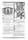
2.1 Front panel
In this chapter we will describe various control elements of
your equalizer. All controls and connectors are explained in
detail, and you will also find useful hints on how to best use
them. Since the three equalizers in the FBQ series are fairly
similar, lets start with the control elements of the FBQ1502 and
the FBQ3102 that are similar to the control elements found on the
FBQ6200. The FBQ6200 additionally features extra control
elements that will be explained in detail later on.
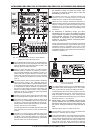
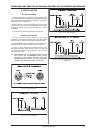
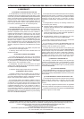
The INPUT/OUTPUT LEVEL METER lets you keep an eye
on the signal level in order to avoid distortion. Depending
on the position of the I/O METER IN/OUT switch , the
display shows either the input or the output signal (switch
depressed) level. When the signal level reaches roughly
+18 dB, that is, 3 dB below clipping starts to occur, the red
CLIP LED lights up.
The level meter on the FBQ1502 displays only the output
signal level.
+ Attention: extreme frequency boosts in connection
with a high input signal level may lead to overdriving
your equipment. Should this occur, it is necessary
to reduce the input signal level by using the INPUT
control.
2. CONTROL ELEMENTS AND CONNECTORS