


7
DVI, Audio & RS-232 Extender with EDID Management
7
2. Installation
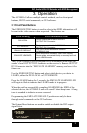
2.1 Required Cables
The video cables are DVI male to male. The audio cables are 3.5mm mini-
stereo. When connecting to a PC’s serial port for remote control of the DVI
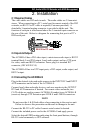
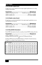
extender, an RS-232 to PC cable is required (Customer provided). A
detachable 3-terminal mating connector is provided with the unit. The
function of each pin is silkscreened above the 3-terminal input connector on
the rear of the unit. Below is a diagram for connecting this port to a PC’s
DB9 serial port.
RS-232 to PC cable
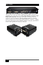
2.2 Inputs & Outputs
The AC2000A-S has a DVI video input, a mini-stereo audio input, a RS232
terminal block, Local DVI output, Local audio output, and two UTP ports
for video, audio and RS232 extension. Power plug is a standard IEC
connector, (IEC 60320 C14)
The AC2000A-R has two UTP input ports, a DVI output, audio output, and
RS232 output.
2.3 Connecting the AC2000A-S
Plug in the desired video and audio sources to the INPUT DVI and INPUT
AUD connectors on the back of the AC2000A-S.
Connect local video and audio devices; such as a monitor to the OUTPUT
DVI and AUD connectors if desired. For remote video and audio; two
CAT5 cables are used to connect AC2000A-S (sender) to an AC2000A-R
(receiver) through UTP Extension port LINK A and LINK B connectors.
NOTE
Do not cross the A & B Link cables when connecting to the receiver unit.
Failure to observe this precaution could result in damage to the unit
Connect the RS-232 to PC cable if remote serial control is desired.
Connect the included power cord to the AC2000A-S and apply power.
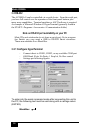
Select the desired EDID routing path using the front panel buttons, through
RS-232 serial commands, or GUI software.