


4
Before use
Part names and
functions
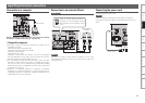
Connections
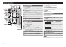
Basic
operations
Effector
function
Fader
Start function
USB settings
Troubleshooting
IndeX
specifications
System diagram
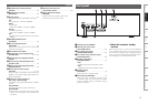
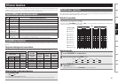
W6 MIC/AUX1 input selection button
(SELECT) ························································ (9)
W7 MIC/AUX1 input display
(MIC/AUX1) ··················································· (9)
W8 SIG/PK display ··············································(9)
Signal/peak meter for MIC/AUX1 input level.
Off:
• No signal input. (Less than -60dBFS)
Green:
• Signal Input
(More than -60dBFS – less than -20dBfS)
Orange:
• Suitable Input Level
(More than -20dBFS – less than -6dBFS)
Red:
• Excessively high signal input level (more than
-6dBFS)
W9 DUCKING ON/OFF button
(DUCKING) ····················································(9)
E0 Mic trim adjustment knob
(MIC TRIM) ····················································(9)
Adjusts the input level for the mic input signal
and AUX1 input signal.
E1 Mic ON/OFF button (MIC) ···························(9)
E2 Channel input source selection knob
(SOURCE SEL) ··································(9, 12, 15)
E3 Channel input level adjustment knob
(LEVEL) ··························································(9)
E4 Channel isolator EQ adjustment knob
(HI, MID, LOW) ··············································(9)
E5 Master output level adjustment knob
(MASTER LEVEL) ··········································(9)
E6 Master effect insertion button
(EFX INS) ···············································(11, 14)
When this button is pressed, various effects are
applied to the master output signal. Flashes for
target AUTO BPM
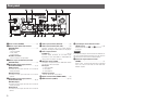
E7 Channel cue master level meter
(CH1, CH2, L/CUE, R/PGM)
The display can be switched between 2 display
modes.
Split CUE OFF:
• Displays the master output volume level.
Split CUE ON:
• Displays the volume level for the right channel
master CUE (monaural) and left channel CUE
(monaural).
E8 Channel cue master level
meter display switch ································· (14)
E9 Master level mode display
(MASTER)
• Lights red for the master output mode.
• Off for the channel input mode.
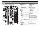
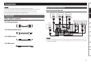
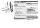
Front panel
ewq
u t ry
q Headphone jack (PHONES)
w Channel fader start switch
(CH FADER START) ····································(12)
e Cross fader start switch
(CROSS FADER START) ·····························(12)
r Cross fader torque adjustment hole
(FLEX FADAR ADJ.) ····································(13)
t Standby mode switch
(STANDBY MODE) ········································(4)
• ON:
Enables the automatic standby function.
• OFF:
Disables the automatic standby function.
y Standby display
(STANDBY) ···················································· (4)
Lights red when in standby mode.
u Restart button (RESTART) ··························· (4)
While this button is pressed when the unit is
in standby mode from the automatic standby
function, standby mode is cancelled, and the
power switches on.
n About the automatic standby
function
While the power is on, if the unit is not operated
(*) for approximately 8 hours, or if there is no input
from the current input source for approximately 8
hours, the unit automatically enters standby mode.
z: Excluding the mic trim adjustment knob.
Top panel