


. . . . .
Voltage regulators
www.digiembedded.com 13
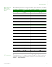
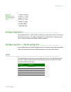
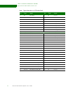
Receiver
Sensitivity and
Transmit Output
Power
-71 dBm @ 54 Mbps
-81 dBm @ 11 Mbps
-88 dBm @ 6 Mbps
-93 dBm @ 1 Mbps
13.8 dBm OFDM
17 dBm PSK/CCK
. . . . . . . . . . . . . . . . . . . . . . . . . . . . . . . . . . . . . . . . . . . . . . . . . . . . . . . . . . . . . . . . . . . . . . . . . . . . . . . . . .
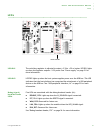
Voltage regulators
The module takes in 3.3V±9% (3.00V to 3.60V) as its main input power. This power is
filtered and used as a 3.3V supply to portions of the digital logic. This power also
acts as input to dedicated on-board voltage regulators.
. . . . . . . . . . . . . . . . . . . . . . . . . . . . . . . . . . . . . . . . . . . . . . . . . . . . . . . . . . . . . . . . . . . . . . . . . . . . . . . . . .
Voltage monitor — Reset generator
The module does not provide a voltage monitor or automatic reset signal generator;
rather, the module uses a reset signal generated by the host system board.
. . . . . . . . . . . . . . . . . . . . . . . . . . . . . . . . . . . . . . . . . . . . . . . . . . . . . . . . . . . . . . . . . . . . . . . . . . . . . . . . . .
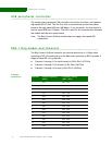
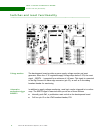
LEDS
The module does not have any on-board LEDs, but it drives the LED_WLAN# signal
(pin 44) to indicate WLAN association and transmit/receive activity. This table
shows the different LED states:
LED state Indication
Off Not powered on
On Associated and authenticated
Slow blink Not associated or authenticated
Intermittent blink Transmit/receive activity