


5
Contents
. . . . . . . . . . . . . . . . . . . . . . . . . . . . . . . . . . . . . . . . . . . . . . . . . . . . . . . . . . . . . . . . . . . . .
Chapter 1:About the Module..................................................................9
Features.......................................................................................... 9
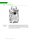
What’s on the module? ...................................................................... 10
Digi Connect Wi-Wave module edge connector................................... 10
Digi Connect Wi-Wave module edge connector: Pinout ......................... 11
U.FL connectors........................................................................ 11
USB peripheral controller ................................................................... 12
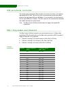
802.11b/g modes and channels ............................................................ 12
Channel allocations ................................................................... 12
Receiver Sensitivity and Transmit Output Power................................. 13
Voltage regulators............................................................................ 13
Voltage monitor — Reset generator ....................................................... 13
LEDS ............................................................................................ 13
Power........................................................................................... 14
DISABLE signal.......................................................................... 14
Chapter 2: About the Development Board ...........................................15
What’s on the development board ........................................................ 15
Features................................................................................. 15
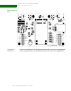
The development board .............................................................. 16
Unpopulated components ............................................................ 16
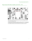
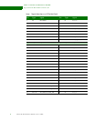
Digi Connect Wi-Wave module connector, J52 .......................................... 17
LEDs ............................................................................................ 19
LED DS1 ................................................................................. 19
LED DS2 ................................................................................. 19
Debug (signal) breakout header LEDs .............................................. 19
Switches and reset functionality........................................................... 20
Voltage monitor........................................................................ 20
Alternative methods to trigger RESET# ............................................ 20
Power supply .................................................................................. 21
Input power jack, J3 .................................................................. 21
Input power supply .................................................................... 21
JTAG Breakout Header, P20 ................................................................ 22
JTAG breakout header signal map .................................................. 22
USB peripheral interface, J4................................................................ 23