


. . . . .
ABOUT THE DEVELOPMENT BOARD
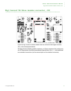
LEDs
www.digiembedded.com 19
. . . . . . . . . . . . . . . . . . . . . . . . . . . . . . . . . . . . . . . . . . . . . . . . . . . . . . . . . . . . . . . . . . . . . . . . . . . . . . . . . .
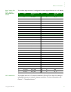
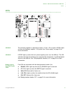
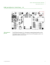
LEDs
LED DS1 The switching regulator is adjusted to output +3.3V
DC
± 5% or better. LED DS1 lights
up when the regulator outputs +3.3V power. See “Power supply” on page 21 for
more information.
LED DS2 LED DS2 lights up when the host system supplies power over the USB bus. This LED
indicates that the host platform has recognized the attachment of a USB peripheral
device on the USB bus. See “USB peripheral interface, J4” on page 23 for more
information.
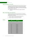
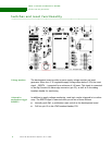
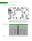
Debug (signal)
breakout header
LEDs
Five LEDs are associated with the debug breakout header (J4):
DISABLE, DS3: Lights up when the W_DISABLE# signal is asserted.
RST, DS4: Lights up when the RESET# signal is asserted.
WAN, DS5: Reserved for future use.
LAN, DS6: Lights up when the module drives the LED_WLAN# signal.
PAN, DS7: Reserved for future use.
See “Debug breakout header, P21” on page 24 for more information.
LEDs: DS3-DS7