


. . . . .
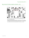
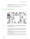
ABOUT THE DEVELOPMENT BOARD
U.FL and RP-SMA connectors
www.digiembedded.com 25
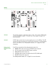
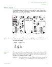
assert the W_DISABLE# signal to the module, place a jumper between either pins 18
and 20 or pins 19 and 20.
As an alternative, you can drive this pin with a low voltage TTL or CMOS driver.
When asserted, W_DISABLE# lights the DISABLE LED, DS3.
. . . . . . . . . . . . . . . . . . . . . . . . . . . . . . . . . . . . . . . . . . . . . . . . . . . . . . . . . . . . . . . . . . . . . . . . . . . . . . . . . .
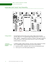
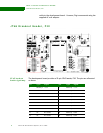
U.FL and RP-SMA connectors
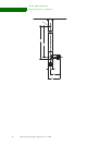
U.FL connectors The development board has two U.FL connectors that pair with two RP-SMA
connectors. U.FL connector P1 pairs with RP-SMA connector J1;U.FL connector P2
pairs with RP-SMA connector J2.
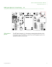
U.FL cables The development kit includes two U.FL-to-U.FL cables that can be used to connect
the module and development board. The number of cables used depends on
whether one antenna is used to transmit and receive or two antennas are used
(diversity receive).
Single antenna configuration: Connect one end of the U.FL cable to connector P1
on the development board and the other end of the cable to connector P1 on the
Digi Connect Wi-Wave module.
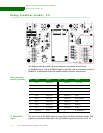
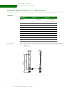
Dual antenna configuration: In addition to the connections outlined in the Single
antenna configuration, connect one end of the second U.FL cable to connector P2