


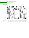
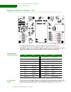

ABOUT THE DEVELOPMENT BOARD
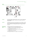
Switches and reset functionality
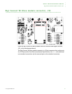
20 Connect Wi-Wave Hardware Reference, Rev A 2/2008
. . . . . . . . . . . . . . . . . . . . . . . . . . . . . . . . . . . . . . . . . . . . . . . . . . . . . . . . . . . . . . . . . . . . . . . . . . . . . . . . . .
Switches and reset functionality
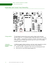
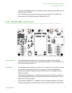
Voltage monitor The development board provides a power supply voltage monitor and reset
generator. When the +3.3V regulated supply voltage drops below 2.93V, the reset
signal — RESET# — is asserted for a minimum of 140 msec. This signal is connected
to the Digi Connect Wi-Wave edge connector (pin 22), as well as to the debug
breakout header for monitoring.
Alternative
methods to trigger
RESET#
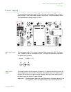
In addition to supply voltage monitoring, reset logic can be triggered in two other
ways. The RESET# signal is asserted when you do one of these actions:
Manually push SW1, a pushbutton reset switch on the development board
Pull low pin 15 on the JTAG breakout header, P20.