


25
MIDI implementation
1. Note Mode setting
* The Note Mode setting lets you use MIDI note numbers to switch inputs.
* Use a system exclusive message to set the Note Mode.
* If the Note Mode is set to 49Keys Mode or Assign Mode, the velocity value of the note
message will vary the transition time.
* The velocity value will control the transition time only when switching to the “A”
channel if the video fader is at “A,” or when switching to the “B” channel if the video
fader is at “B.”
* There are four Note Modes.
●1-1. OFF
* Note Mode is not used.
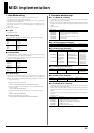
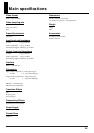
●1-2. 49Keys Mode
* If you select 49Keys Mode, the V-1 will be controlled by the following note numbers.
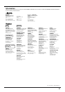
●1-3. Assign Mode
* In Assign Mode, the V-1 will be controlled by the range of note numbers you specify
using Note Assign. The factory settings are shown below.
* If you want to change the values used in Assign Mode, switch the Note Mode to Note
Assign and make the desired assignments.
●1-4. Note Assign
* In this mode you can modify the settings used in Assign Mode. You must specify two
note numbers; a lower limit and an upper limit. When you have specified these
numbers, the corresponding range of note numbers will be assigned to “A” channel 1, 2,
3,... through “B” channel 4.
(1) Change the Note Mode to Note Assign.
<Example> F0H 41H 10H 00H 6FH 12H 12H 00H 01H 03H 6AH F7H
(2) Specify the range of notes by transmitting two note-on messages with a velocity
value of 1 or higher.
<Example> 90H 10H 7FH 90H 20H 7FH
(3) Transmit two note-on messages with a velocity of 0 for the specified range of
notes.
<Example> 90H 10H 00H 90H 20H 00H
(4) Change the Note Mode back to Assign Mode.
<Example> F0H 41H 10H 00H 6FH 12H 12H 00H 01H 02H 6BH F7H
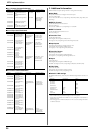
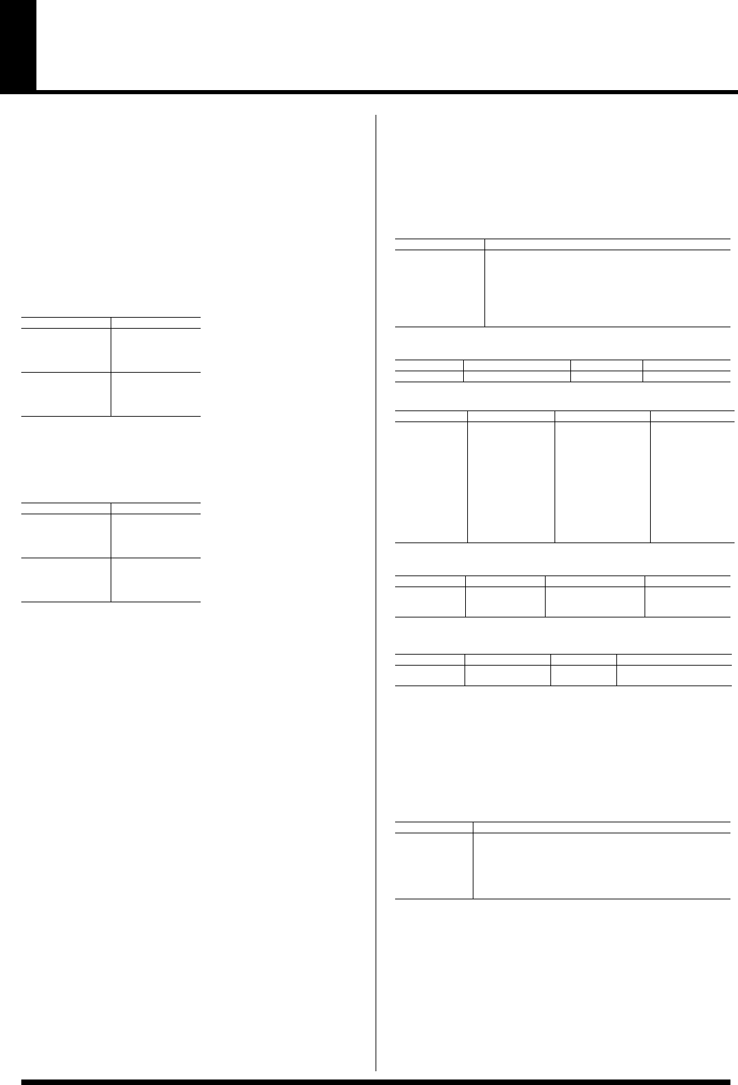
2. Parameter address map
●2-1. V-1 (Model ID = 00H 6FH)
* For addresses marked by #, divide the data and transmit it as two bytes; an upper nibble
(upper 4 bits) and lower nibble (lower 4 bits).
* Example) If the original data is BCH, send 0BH as the first byte, and send 0CH as the
second byte. For reception, the data will be ignored unless the two bytes are received
together.
* DEVICE ID = 10H
●2-1-1. System Common Preference
●2-1-2. Fader Control Preference
●2-1-3. Effects Control Preference
●2-1-4. Fader Control Parameter
●2-2. V-LINK (Model ID = 00H 51H)
* For addresses marked by #, divide the data and transmit it as two bytes; an upper nibble
(upper 4 bits) and lower nibble (lower 4 bits).
* Example) If the original data is BCH, send 0BH as the first byte, and send 0CH as the
second byte. For reception, the data will be ignored unless the two bytes are received
together.
* If the value is shown as..., this is a parameter not supported by the V-1. It will be ignored
if received.
* DEVICE ID = 10H
Note No. Input
24H A Ch. 1
26H A Ch. 2
28H A Ch. 3
29H A Ch. 4
2BH B Ch. 1
2DH B Ch. 2
2FH B Ch. 3
30H B Ch. 4
Note No. Input
24H(C +2) A Ch. 1
25H(C#+2) A Ch. 2
26H(D +2) A Ch. 3
27H(D#+2) A Ch. 4
28H(E +2) B Ch. 1
29H(F +2) B Ch. 2
2AH(F#+2) B Ch. 3
2BH(G +2) B Ch. 4
Start Address Description
00H 00H 00H System Common Preference Area (See 2-1-1)
01H 00H 00H Fader Control Preference Area (See 2-1-2)
02H 00H 00H Effects Control Preference Area (See 2-1-3)
03H 00H 00H Reserved Area
12H 00H 00H Fader Control Parameter Area (See 2-1-4)
13H 00H 00H Reserved Area
14H 00H 00H Reserved Area
Address Parameter Name Sys.Ex.Value Meaning of Value
00H 00H 00H MIDI Receive Channel 00H - 10H. 1 - 16 Ch, OFF
Address Parameter Name Sys.Ex.Value Meaning of Value
#01H 10H 00H Tx/Rx Setting
(Transition Time)
01H-05H,07H-1FH,
40H-5FH,D0H,E0H,FFH
Control Change,
Channel Press,
Pitch Bend, OFF
#01H 10H 02H Tx/Rx Setting
(Video Fader)
01H-05H,07H-1FH,
40H-5FH,D0H,E0H,FFH
Control Change,
Channel Press,
Pitch Bend, OFF
#01H 10H 04H Tx/Rx Setting
(MIX, WIPE /
P in P)
01H-05H,07H-1FH,
40H-5FH,D0H,E0H,FFH
Control Change,
Channel Press,
Pitch Bend, OFF
#01H 10H 0AH Tx/Rx Setting
(Output Fade)
01H-05H,07H-1FH,
40H-5FH,D0H,E0H,FFH
Control Change,
Channel Press,
Pitch Bend, OFF
Address Parameter Name Sys.Ex.Value Meaning of Value
#02H 10H 00H Tx/Rx Setting
(Superimpose)
01H-05H,07H-1FH,
40H-5FH, D0H, E0H,FFH
Control Change,
Channel Press,
Pitch Bend, OFF
Address Parameter Name Sys.Ex.Value Meaning of Value
12H 00H 01H Note Mode 00H - 03H OFF,49Keys Mode,
Assign Mode, Note Assign
Start Address Description
00H 00H 00H DV-7PR Presenter Reserved Area
10H 00H 00H V-LINK System Preference Area (See 2-2-1)
10H 10H 00H V-LINK Clip Control Preference Area (See 2-2-2)
10H 20H 00H V-LINK Effects Control Preference Area (See 2-2-3)
10H 30H 00H V-LINK Reserved Area
11H 00H 00H DV-7PR Presenter Reserved Area