MGP 464 • Quick Start
QS-2
PRELIMINARY
Quick Start — MGP 464, cont’d
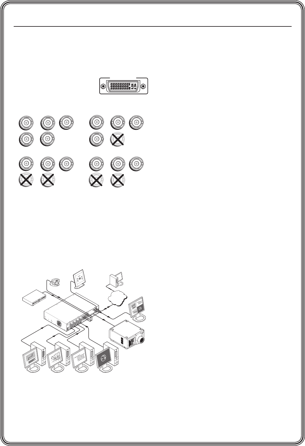
Step 4
Attach an output device to the RGBHV/YUV
BNC connectors and/or to the DVI output
connector (shown below).
N
Analog is not
available on this
DVI connector.
BNC output connectors
Step 5
Plug the MGP 464, input devices, and output
devices into a grounded AC source, and power
on the input and output devices. The following
diagram shows an example of an MGP 464 DI
application.
MGP 464 DI connection diagram
Camera
Extron
MGP 464 DI
Four Window
Multi-Graphic Processor
Control System
DVD
Remote User and
Administration Control
.5A MAX
1
0
0
-
240
50/60 Hz
1
INPUT 1-DVI-D
R
R-Y
G/Y
VID
H/HV
V
H/HV
B/C
B-Y
2
R
R-Y
G/Y
VID
H/HV
V
H/HV
B/C
B-Y
3
R
R-Y
G/Y
VID
H/HV
V
H/HV
B/C
B-Y
4 5
R
R-Y
G/Y
VID
H/HV
V
H/HV
B/C
B-Y
R/
R-Y
VID
Y
6
VID
R-Y
C
7
VID
B-Y
8
VID
Y
9
VID
R-Y
C
10
VID
B-Y
11
VID
Y
12
VID
R-Y
C
13
VID
B-Y
14
VID
Y
15
VID
R-Y
C
16
VID
B-Y
17
VID
Y
18
VID
R-Y
C
19
VID
B-Y
G/Y
B/
B-Y
H/
HV
V
INPUT 2-DVI-D
INPUT 3-DVI-D
INPUT 4-DVI-D
DVI BACKGROUND
DVI OUTPUT
RGB/Y, R-Y, B-Y OUTPUT
RS-232/422
LAN
R
VIRTUAL VIDEO INPUTS
RGB VIDEO INPUTS
PC PC PC PC
Preview
Monitor
TCP/IP
Network
Projector
ANAHEIM
Disneyland
BALL RD.
LINCOLN AV.
STATE COLLEGE BLVD.
ANAHEIM BLVD.
LEWIS ST.
Anaheim
Stadium
KATELLA AV.
CERRITOS AV.
DOUGLAS RD.
EAST ST.
HASTER ST.
WEST ST.
Extron
5
57
ANAHEIM
Disneyland
BALL RD.
LINCOLN AV.
STATE COLLEGE BLVD.
ANAHEIM BLVD.
LEWIS ST.
Anaheim
Stadium
KATELLA AV.
CERRITOS AV.
DOUGLAS RD.
EAST ST.
HASTER ST.
WEST ST.
Extron
5
57
Step 6
Use the LCD menu screens and Adjust knobs to
congure the MGP 464 and adjust the picture
controls.
(See the following section, “Setting Up the
MGP 464” and “Adjusting the Picture Controls,”
in the next section. See chapter 2, “Installation,”
for installation instructions, chapter 3,
“Operation,” for front panel operation
information, chapter 4, “Software Conguration
and Control,” for control via the RS-232/422
interface, and chapter 5, “HTML Conguration
and Control,” for control via the MGP 464 Web
pages..
Setting Up the MGP 464
After you have installed and connected the
MGP 464, follow these steps to congure and
adjust the unit to get it ready for use.
Conguring the MGP
Press the Menu button to access the Main menu,
shown on the next page. Then, repeatedly press
the Menu button to cycle through the menus
to access the Input Configuration, Output
Configuration, and Advanced Configuration
menus to perform steps 1 through 4.
Step 1
Use the Input Conguration menu to congure
inputs 1 through 4.
N
The virtual inputs (5 through 19) can
be configured only via the Windows-
based control software, SIS commands,
or the Web pages. For information on
configuring those inputs, see chapter 4,
“Software Configuration and Control,”
and chapter 5, “HTML Configuration
and Control.”
Step 2
Use the Output Conguration menu to congure
the output signal type and the output rate for the
desired resolution.
Step 3
From the Advanced Configuration menu, Test
Pattern submenu, select the Alternating Pixels
(Alt. Pixels) test pattern. Adjust your display’s
active pixels, total pixels, and pixel phase settings
for optimal picture quality.
R
/R-Y
G
/Y
B
/B-Y
H
/HV
V
R
/R-Y
G
/Y
B
/B-Y
H
/HV
V
R
/R-Y
G
/Y
B
/B-Y
H
/HV
V
R
/R-Y
G
/Y
B
/B-Y
H
/HV
V
RGBHV RGBS
RGsB HD YUV Component Video


