


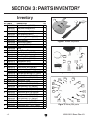
-12-
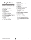
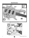
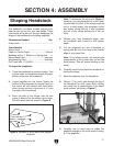
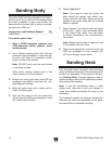
H8180/H8181 Bass Guitar Kit
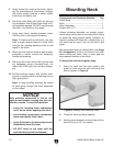
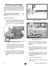
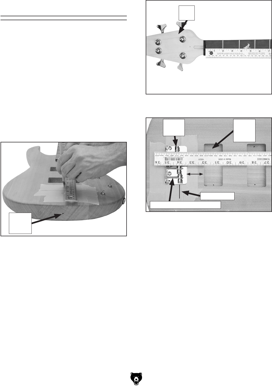
Figure 14. Example of measuring 34" from nut
along center line.
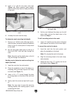
Figure 15. Bridge point, and lower G string
saddle adjustment screw.
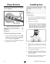
Nut
Slot
Positioning Bridge
The following steps require you to mark the guitar
body. To avoid damaging the finish, place mask
-
ing tape on the guitar body and gently mark the
tape.
Components and Hardware Needed: Qty
Guitar Body and Neck (Assembled) .................. 1
Bridge ................................................................
1
To position the bridge
:
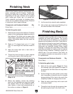
1. Place a 36" long straightedge over the center
of the fretboard inlays and over the body, so
it aligns with the strap button hole, then mark
the center line on the guitar body (Figure
13).
—If the strap button hole is not pre-drilled,
or you do not want to use the strap button
hole as a center line marker, place a ruler
across the body at several locations and
mark the center line
.
2. Using the straightedge, measure 34" from
the fretboard side of the nut slot (
Figure
14) along the center line to the bridge point
(Figure 15), and mark this location on the
guitar.
Figure 13. Marking center line.
3. Place the bridge on the body so it is approxi-
mately 1
3
/4" from the bridge pickup cavity
and align it with the center line, as shown in
Figure 15.
4. Using a Phillips head screwdriver, turn the
G string saddle adjustment screw so the set
screws shown in
Figure 15 are centered over
the bridge point.
5. Using a Phillips head screwdriver, turn the
lower saddle adjustment screw so the set
screws shown in
Figure 15 are centered over
the bridge point.
6. Mark the bridge mounting holes.
7. Using a
3
/32" bit, drill the five bridge mounting
holes
7
/8" deep.
Bridge
Pickup
Cavity
Strap
Button
Hole
Set
Screw
Bridge Point
Lower Saddle Adj. Screw
1
3
⁄4"