


-14-
H8180/H8181 Bass Guitar Kit
Wiring Pickups &
Output Jack
4. Solder the audio jack wires onto the output
jack, as shown in the Wiring Diagram on
Page
28 and the Electrical Components on
Page 27
.
5. Insert the ground wire through the hole in the
control cavity and through the hole in the top
of the body. Temporarily secure the end of
the ground wire with masking tape.
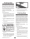
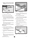
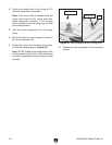
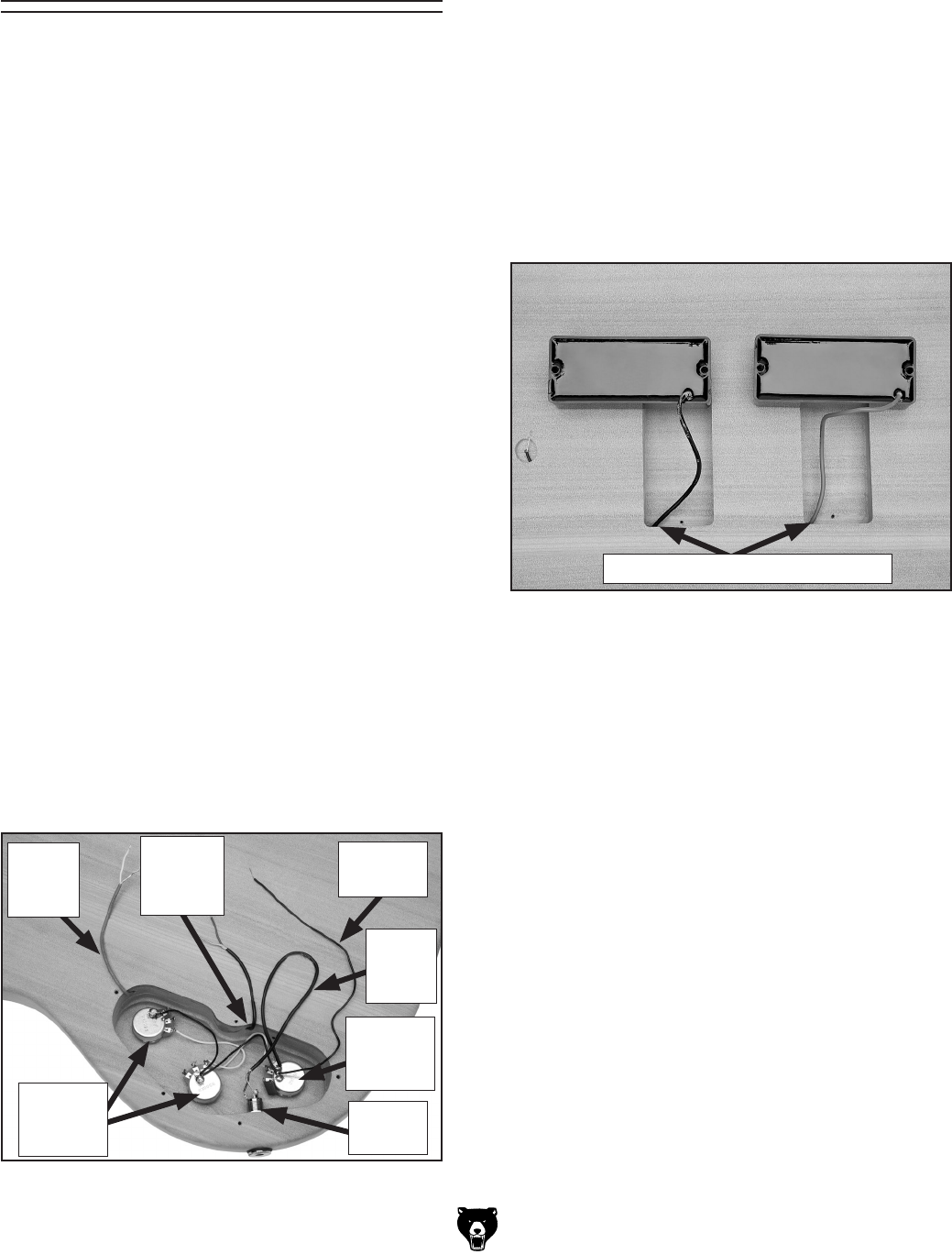
6. Flip the guitar body face up, thread the pickup
wires through the holes in the pickup cavities
(Figure 20) and temporarily tape the pickups
to the body with masking tape.
This guitar comes with a wiring harness that has
most of the components soldered in place. You
only need to solder the pickup wires onto the
volume control pots and the audio jack wire onto
the output jack. If done incorrectly, the soldering
can damage the components. If you are unsure
of your skills, do your research, practice on scrap
wires, or take it to someone with experience.
Refer to the Wiring Diagram on Page
28 and the
Electrical Components on Page 27
while wiring
the pickups and output jack.
Components and Hardware Needed: Qty
Guitar Body .......................................................
1
Wiring Harness ..................................................
1
Bridge Pickup ....................................................
1
Neck Pickup ......................................................
1
Output Jack .......................................................
1
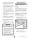
To wire the pickups:
1. Remove the hex nut and flat washer from
each control pot on the wiring harness.
2. Insert the control pots through the holes in
the control cavity, and secure the pots on the
front of the guitar with the hex nuts and wash
-
ers removed in Step 1
.
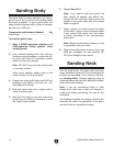
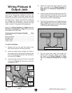
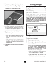
3. Insert the output jack into the hole in the end
of the body (
Figure 19) and secure it with the
included hex nut.
Figure 19. Wires threaded through control
cavity.
Volume
Control
Pots
Neck
Pickup
Wire
Bridge
Pickup
Wire
Output
Jack
7. Flip the guitar face down and solder the
pickup wires onto the volume control pots,
as shown in the Wiring Diagram on Page
28
and the Electrical Components on Page
27
.
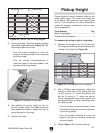
Figure 20. Pickup cavities.
Location to Insert Pickup Wires
Tone
Control
Pot
Ground
Wire
Audio
Jack
Wire