


TK-260G/270G
19
CIRCUIT DESCRIPTION
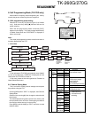
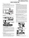
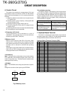
Fig. 7 Microphone amplifier
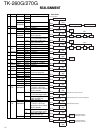
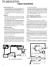
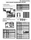
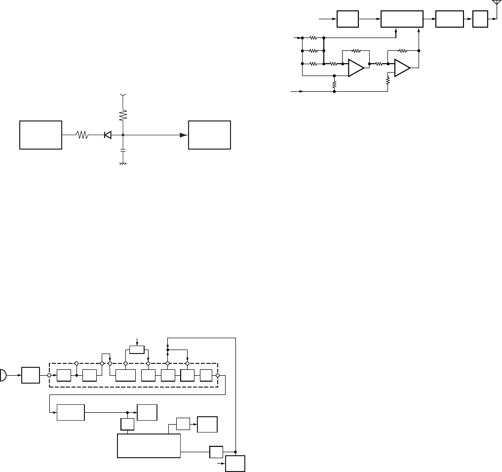
Fig. 8 Drive and final amplifier and APC circuit
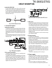
3) UNLOCK DETECTOR
If a pulse signal appears at the LD pin of IC2, an unlock
condition occurs, and the DC voltage obtained form D1,
R1, and C6 causes the voltage applied to the microprocessor
to go low. When the microprocessor detects this condition,
the transmitter is disabled, ignoring the push-to-talk switch
input signal.(See Fig. 6)
Fig. 6 Unlock detector circuit
4. Transmitter System
1) Microphone amplifier
The signal from the microphone passes through the limitter
circuit in D23, and through the high-pass filter, the ALC
circuit, the low-pass filter, the high-pass filter, and pre-
emphasis/IDC circuit IC14. When encoding DTMF, the mute
switch (Q35) is turned OFF for muting the microphone input
signal.
The signal passes through the D/A converter (IC17) for the
maximum deviation adjustment, and goes to the VCXO
modulation input.
IC2
LD
PLL IC
D1
C6
R1
5C
IC13
UL
CPU
12
HPF
LPF HPF IDC
PRE
EMP
ALC
COMP
SW
LIMIT
D23
MIC
IC14
15
16
18 19
Q35
MUTE
DTMF/
2 TONE
98
6
D/A
IC13
CPU
IC17
QT/DQT
IC15
(2/2)
2
TOTCXO
20
TOVCO
22
VCO
AF
AMP
TCXO
(RX Audio)
LPF
LPF
LPF
X1
DTMF/ 2 TONE
3) APC circuit
The APC circuit always monitors the current flowing through
the RF power amplifier (IC1) and keeps a constant current.
The voltage drop at R56, R57 and R58 is caused by the
current flowing through the RF power amplifier and this
voltage is applied to the differential amplifier IC3(1/2).
IC3(2/2) compares the output voltage of IC3(1/2) with the
reference voltage from IC13, and the output of IC3(2/2)
controls the VGG of the RF power amplifier to make both
voltages the same.
The change of power high/low is carried out by the change
of the reference voltage.
4) Encode signaling
(1) QT/DQT (Low-speed data)
QT,DQT data of the TOTCXO Line is output form pin 20 of
the CPU. The signal passes through a low-pass CR filter
and goes to the TCXO(X1).
The QT,DQT data of the TOVCO Line is output form pin 22
of the CPU. The signal passes through a low pass CR filter,
mixes with the audio signal, and goes to the VCO modulation
input. TX deviation is adjusted by the CPU. (See fig.7)
(2) DTMF/2 TONE (High-speed data)
High-speed data is output from pin 2 of the CPU. The signal
passes through a low-pass CR filter, and provides a TX
and SP out tone, and is then applied to the audio processor
(IC14). The signal is mixed with the audio signal and goes
to the VCO.
TX deviation is adjusted by the CPU. (See fig.7)
5. Power supply
There are five 5V power supplies for the microprocessor:
5V,5M,5C,5R, and 5T. 5V is always output while the power
is on. 5M is always output, but turns off when the power is
turned off to prevent malfunction of the microprocessor.
5C is a common 5V and is output when SAVE is not set to
OFF.
5R is 5V for reception and output during reception.
5T is 5V for transmission and output during transmission.
2) Drive and Final amplifier
The signal from the T/R switch (D5 is on) is amplified by the
drive amplifier (Q6) to 50mW.
The output of the drive amplifier is amplified by the RF power
amplifier (IC1) to 5.0W (1W when the power is low). The
RF power amplifier consists of two MOS FET stages. The
output of the RF power amplifier is then passed through the
harmonic filter (LPF) and antenna switch (D3 is on) and
applied to the antenna terminal.
From
T/R SW
(D5)
DRIVE
AMP
RF
POWER AMP
LPF
ANT
SW
D3
ANT
VGG
Q6 IC1
VDD
R56
R57
R58
+B
IC3
(1/2)
IC3
(2/2)
APC
(IC13)