


5
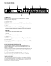
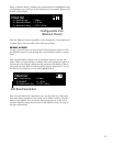
the ReAR PANeL
1. POWER JACK
Standard 3-pin IEC power connector. 100-240V, 50-60Hz automatic
switching to correct voltage range.
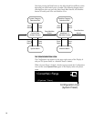
2. ETHERNET INPUT
This RJ-45 connection is used to network PCM92 devices and control them
via Ethernet.
3. MIDI IN
Receives MIDI information from other MIDI equipment such as master
keyboard controllers, MIDI foot controllers, sequencers and synthesizers.
MIDI THRU
Passes any MIDI data received without change.
MIDI OUT
Transmits MIDI data to other equipment.
4. AES/EBU In/Out
AES/EBU format digital connectors conform to AES professional standards.
5. ANALOG IN/OUT
Output impedance is 30Ω, electronically balanced, and levels up to +20dBu
maximum full scale.
6. FOOT CONTROLLER/FOOTSWITCH JACKS
The Footswitch jack supports a momentary footswitch allowing you to
control switchable settings. Connect a footswitch to the Footswitch jack
using a 1/4” TRS cable.
The Foot Control jack supports a foot pedal or expression pedal allowing you
to control sweepable parameters. Connect a foot pedal to the Foot Control
jack using a 1/4” TRS cable.
See the Footswitch and Foot Pedal Functionality section for more
information about using a Footswitch or Foot Pedal with the PCM92.
7. WORD CLOCK INPUT
This connection allows the PCM92 to lock to a master system clock. It is
not terminated. For best results we recommend using “T” connectors when
setting up a BNC Word Clock network and terminating the end of of this
network with a 75 ohm BNC terminator.
1 2
76
543