


12 Onyx 1220i
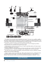
as well as to solo, and add to aux send 1 and 2. This
is routed using the FW/line input selector [23] on
channels 11 and 12. This is useful for live
performances, where those 2 channels might have,
for example, a software synthesizer you are
triggering from a MIDI keyboard, and you want to
treat the softsynth as "just another instrument," with
equal processing and routing options as the hardware
keyboards coming into the other channels.
The FireWire interface works with both PC (using
ASIO for Windows XP and Vista) and Mac (Core Audio
for Mac OS 10.4.11 or higher).
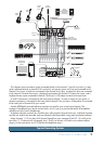
4. LEFT/RIGHT XLR MAIN OUTPUTS
These male XLR connectors provide a balanced line-
level signal that represents the end of the mixer chain,
where your fully mixed stereo signal enters the real
world. Connect these to the inputs of your main power
amplifi ers, powered speakers, or serial effects
processor (like a graphic equalizer or compressor/
limiter). It provides a fully balanced signal that is the
same level as the 1/4" TRS main out jacks [13] on the
top panel.
5. MAIN OUTPUT LEVEL
When this switch is out (+4 dB), the XLR main
outputs [4] provide a "+4 dBu" line-level signal. You
can then connect these outputs to the line-level inputs
of power amplifi ers, powered loudspeakers, or serial
processors.
When the switch is pushed in (mic), the XLR main
outputs are attenuated to microphone level. You can
then connect these outputs safely to the microphone
inputs of another mixer, providing a submix for
keyboards or drums, for example, in a live sound
application. The main outputs can then be plugged
directly into a stage snake, and appear back at the front
of house console like any other microphone level source.
When mic is engaged, you can safely plug the
XLR main output into a mixer's microphone
input, even if it provides 48 V phantom power.
The switch is recessed, to reduce the chance of
accidently turning it on or off when plugging things in.
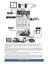
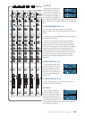
6. AUX SEND 1 and 2
These 1/4" TRS connectors allow you to send balanced
or unbalanced line-level outputs to external effects
devices, headphone amplifi ers, or stage monitors. These
could either be passive stage monitors powered by an
external amplifi er, or powered stage monitors with
built-in power amplifi ers.
Aux send 1 and aux send 2 are independent of each
other, so you can set up two separate aux mixes.
The aux 1 send signal is the sum (mix) of all the
channels whose aux 1 send control [29] is set to more
than minimum. The aux 2 send is the sum of all the
channels whose aux 2 send control is set to more than
minimum. The overall aux output level can be adjusted
with the aux send master controls [42].
The aux sends can either be pre or post fader,
depending on the position of the pre/post switches [43].
For stage monitor work, use pre, so the stage monitors
do not increase in volume when the channel faders are
adjusted. Imagine how upsetting that can be to big hairy
drummers. This allows you to set up the monitor mix
and levels just right, and not have it change every time a
channel fader is adjusted.
For external processors, use post. In this way, the feed
to external processors will vary with the channel faders,
so the level of any returned effect (like an echo) will
also change if the channel fader is changed, keeping
them in the same ratio (wet/dry).
7. AUX RETURN 1 and 2
These 1/4" TRS stereo input connectors allow you to
add the stereo processed output from external effects
processors or other devices to the main mix.
Level adjustment of the incoming signals is made with
the aux return controls [44].
The signals going into aux return 2 can also be added
to aux send 1 by engaging the return to aux 1 switch
[45]. For example, you could add effects from an
external effects processor to your stage monitors.
You can also use these inputs to add any stereo line-
level signals to your main mix, so it could be another
line-level source, not just an effects processor.
If you are connecting a mono source, use the left
(mono) aux return input, and the mono signals will
appear on both sides of the main mix.
8. INSERT (Ch. 1-4)
These unbalanced 1/4" jacks on channels 1-4, are for
connecting serial effects processors such as
compressors, equalizers, de-essers, or fi lters. The insert
point is after the gain control [21] and low cut fi lter
[19], but before the channel’s EQ and fader [33]. The
channel signal can go out of the insert jack to an
external device, be processed and come back in on the
same insert jack. To do this requires a standard insert
cable that must be wired thusly:
Tip = send (output to effects device)
Ring = return (input from effects device)
Sleeve = common ground