


11
Owner’s Manual
Owner’s Manual
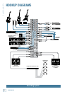
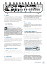
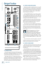
3-4 stereo bus (see MUTE/ALT 3-4 on page 13), Soloed
channels, or the Tape input. The volume is adjustable
with the CONTROL ROOM/SUBMIX [34] fader.
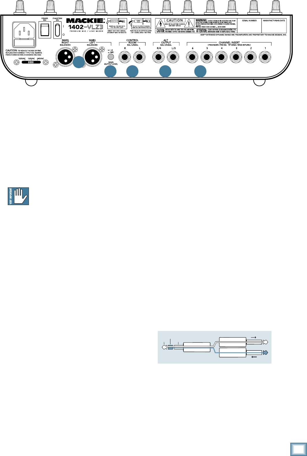
These 1⁄4" jacks are balanced outputs capable of de
-
livering 22 dBu into a 600 ohm balanced or unbalanced
load.
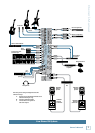
16. ALT 3–4 OUTPUT
The output here is the sum of any channels that have
the MUTE/ALT 3-4 [25] switch pressed in (see page 13
for the tender details).
These 1⁄4" jacks are balanced outputs capable of de-
livering 22 dBu into a balanced or unbalanced load.
17. CHANNEL INSERT (Channels 1–6 )
These rear-panel jacks are where you connect serial
effects such as compressors, equalizers, de-essers, or
filters. Since most people don’t have more than a few of
these gadgets, we’ve included inserts for just the first
six channels. If you want to use this kind of processing
on channels 7 through 14, simply patch through the
processor before you plug into the 1402-VLZ3.
The channel insert points are after the GAIN [4] and
LOW CUT [3] controls, but before the channel’s EQ
[27] controls and FADER [23]. The send (tip) is low-
impedance (120 ohms), capable of driving any line-level
device. The return (ring) is high-impedance (over 2.5 k
ohms) and can be driven by almost any device.
See Appendix B for details and drawings about Insert
cables, and a diagram showing three ways to use the
jacks.
Besides being used for inserting external devices,
these jacks can also be used as channel direct outputs;
post-GAIN, post-LOW CUT, and pre EQ. In fact, Mackie
mic preamps have become so famous, that people buy
these mixers just to have six of these in their arsenal.
12. PHONES
This stereo jack will drive any standard headphone
to very loud levels. Walkperson-type phones can also be
used with an appropriate adapter. To learn how signals
are routed to these outputs, see SOURCE MATRIX
[33] on page 16. If you’re wiring your own cable for the
PHONES output, follow standard conventions:
Tip = Left channel
Ring = Right channel
Sleeve = Common ground
WARNING: When we say the headphone amp
is loud, we’re not kidding. It can cause per-
manent ear damage. Even intermediate levels
may be painfully loud with some earphones. BE CARE-
FUL! Always move the CTL ROOM/ SUBMIX fader all the
way down before connecting headphones. Keep it down
until you’ve put the phones on. Then turn it up slowly.
Why? “Engineers who fry their ears find themselves with
short careers.”
13. XLR MAIN OUTS
These line-level outputs connect the main mix to the
outside world. Connect them to the balanced inputs of
a power amplifier or powered speakers. See page 16 for
details of the main mix.
These low-impedance outputs are fully balanced
and capable of driving +4 dBu lines with up to 28 dB
of headroom. This output is 6 dB hotter than other
outputs.
14. XLR MAIN OUTPUT LEVEL SWITCH
Engaging this switch reduces the level of the bal-
anced XLR main outputs by 40 dB, so you can feed the
microphone input of, say, another mixer. (You can safely
connect the XLR outputs into an input that provides 48V
phantom power.)
15. CONTROL ROOM
These outputs are provided so you can listen to some-
thing other than the main mix. The source is selected
using the SOURCE MATRIX [33] switches (see page
16). You can choose to listen to the main mix, the Alt
M
I
C
G
A
I
N
0
U
60
-
1
0
d
B
V
+15dB -45dB
M
I
C
G
A
I
N
0
U
60
-
1
0
d
B
V
+15dB -45dB
M
I
C
G
A
I
N
0
U
60
-
1
0
d
B
V
+15dB -45dB
M
I
C
G
A
I
N
0
U
60
-
1
0
d
B
V
+15dB -45dB
M
I
C
G
A
I
N
0
U
60
-
1
0
d
B
V
+15dB -45dB
M
I
C
G
A
I
N
0
U
60
-
1
0
d
B
V
+15dB -45dB
U
OO
+10
U
OO
+20
U
OO
+20
U
O
O
+15
U
O
O
+15
U
O
O
+15
U
O
O
+15
U
O
O
+15
U
O
O
+15
U
O
O
+15
U
O
O
+15
U
O
O
+15
U
O
O
+15
U
O
O
+15
U
O
O
+15
U
O
O
+15
U
O
O
+15
U
O
O
+15
U
O
O
+15
U
O
O
+15
U
O
O
+15
U
O
O
+15
U
O
O
+15
U
+15-15
U
+15-15
U
+15
-15
U
+15-15
U
+15-15
U
+15
-15
U
+15-15
U
+15-15
U
+15
-15
U
+15-15
U
+15-15
U
+15
-15
U
+15-15
U
+15-15
U
+15
-15
U
+15-15
U
+15-15
U
+15
-15
U
+15-15
U
+15-15
U
+15
-15
U
+15-15
U
+15-15
U
+15
-15
U
+15-15
U
+15-15
U
+15
-15
U
+15-15
U
+15-15
U
+15
-15
dB
30
20
10
OO
40
50
5
5
U
60
10
dB
30
20
10
OO
40
50
5
5
U
60
10
dB
30
20
10
OO
40
50
5
5
U
60
10
dB
30
20
10
OO
40
50
5
5
U
60
10
dB
30
20
10
OO
40
50
5
5
U
60
10
dB
30
20
10
OO
40
50
5
5
U
60
10
dB
30
20
10
OO
40
50
5
5
U
60
10
dB
30
20
10
OO
40
50
5
5
U
60
10
dB
30
20
10
OO
40
50
5
5
U
60
10
dB
30
20
10
OO
40
50
5
5
U
60
10
dB
30
20
10
OO
40
50
5
5
U
60
10
dB
30
20
10
OO
40
50
5
5
U
60
10
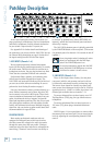
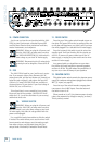
MIC
2
MIC
3
MIC
4
MIC
5
MIC
6
BAL
OR
UNBAL
BAL
OR
UNBAL
BAL
OR
UNBAL
BAL
OR
UNBAL
BAL
OR
UNBAL
BAL
OR
UNBAL
AUX SEND
1
2
1
2
RIGHT
LEFT/MONO
ALL BAL/UNBAL
BAL/UNBAL
L
R
LINE IN 1 LINE IN 2
LOW CUT
75 Hz
18dB/OCT
LOW CUT
75 Hz
18dB/OCT
LINE IN 3
LOW CUT
75 Hz
18dB/OCT
LINE IN 4
LOW CUT
75 Hz
18dB/OCT
LOW CUT
75 Hz
18dB/OCT
LINE IN 5 LINE IN 6
LOW CUT
75 Hz
18dB/OCT
GAINGAIN GAIN GAIN GAIN GAIN
LINE IN 7-8
LINE IN 9-10
LINE IN 11-12
LINE IN 13-14
AUX
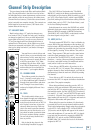
HI
12kHz
MID
2.5kHz
LOW
80Hz
EQ
PAN
AUX
EQ
PAN
AUX
EQ
PAN
AUX
EQ
PAN
AUX
EQ
PAN
AUX
EQ
PAN
AUX
EQ
PAN
AUX
EQ
PAN
AUX
EQ
PAN
AUX
EQ
PAN
SOLO
1
MUTE
ALT 3
–
4 ALT 3
–
4 ALT 3
–
4 ALT 3
–
4 ALT 3
–
4 ALT 3
–
4 ALT 3
–
4 ALT 3
–
4 ALT 3
–
4
L R
HI
12kHz
MID
2.5kHz
LOW
80Hz
SOLO
2
MUTE
L R
HI
12kHz
MID
2.5kHz
LOW
80Hz
SOLO
3
MUTE
L R
HI
12kHz
MID
2.5kHz
LOW
80Hz
SOLO
4
MUTE
L R
HI
12kHz
MID
2.5kHz
LOW
80Hz
SOLO
5
MUTE
L R
HI
12kHz
MID
2.5kHz
LOW
80Hz
SOLO
6
MUTE
L R
HI
12kHz
MID
2.5kHz
LOW
80Hz
SOLO
7-8
MUTE
L R
HI
12kHz
MID
2.5kHz
LOW
80Hz
SOLO
9-10
MUTE
L R
HI
12kHz
MID
2.5kHz
LOW
80Hz
SOLO
11-12
MUTE
L R
HI
12kHz
MID
2.5kHz
LOW
80Hz
SOLO
13-14
MUTE
ALT 3
–
4
L R
L
MONO
MONO
MONO
MONO
R
BAL
OR
UNBAL
L
R
BAL
OR
UNBAL
L
R
BAL
OR
UNBAL
L
R
BAL
OR
UNBAL
TAPE
INPUT
TAPE
OUTPUT
L
R
L
R
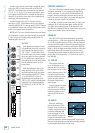
20
10
7
4
2
0
2
4
7
10
20
30
LEVEL
SET
LEFT RIGHT
MAIN OUT
ALT 3–4
TAPE
MAIN MIX
ASSIGN
TO MAIN MIX
SOLO
MODE
LEVEL SET (PFL)
NORMAL (AFL)
C-R/SOURCE
PO48V WER
RUDE
SOLO
LIGHT
MAIN MIXCTL ROOM /SUBMIX
0dB=0dBu
LEVELLEVELLEVEL
-
10
LEVEL
+4
-
10
+4
-
10
+4
-
10
+4
MIC
1
X
D
R
M
I
C
P
R
E
X
D
R
M
I
C
P
R
E
X
D
R
M
I
C
P
R
E
X
D
R
M
I
C
P
R
E
X
D
R
M
I
C
P
R
E
X
D
R
M
I
C
P
R
E
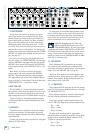
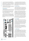
“tip”
This plug connects to one of the
mixer’s Channel Insert jacks.
“ring”
tip
ring
sleeve
SEND to processor
RETURN from processor
(TRS plug)
13
14 15 16 17