


16
140-VLZ3
1402-VLZ3
M
I
C
G
A
I
N
0
U
60
-
1
0
d
B
V
+15dB -45dB
M
I
C
G
A
I
N
0
U
60
-
1
0
d
B
V
+15dB -45dB
M
I
C
G
A
I
N
0
U
60
-
1
0
d
B
V
+15dB -45dB
M
I
C
G
A
I
N
0
U
60
-
1
0
d
B
V
+15dB -45dB
M
I
C
G
A
I
N
0
U
60
-
1
0
d
B
V
+15dB -45dB
M
I
C
G
A
I
N
0
U
60
-
1
0
d
B
V
+15dB -45dB
U
OO
+10
U
OO
+20
U
OO
+20
U
O
O
+15
U
O
O
+15
U
O
O
+15
U
O
O
+15
U
O
O
+15
U
O
O
+15
U
O
O
+15
U
O
O
+15
U
O
O
+15
U
O
O
+15
U
O
O
+15
U
O
O
+15
U
O
O
+15
U
O
O
+15
U
O
O
+15
U
O
O
+15
U
O
O
+15
U
O
O
+15
U
O
O
+15
U
O
O
+15
U
+15-15
U
+15-15
U
+15
-15
U
+15-15
U
+15-15
U
+15
-15
U
+15-15
U
+15-15
U
+15
-15
U
+15-15
U
+15-15
U
+15
-15
U
+15-15
U
+15-15
U
+15
-15
U
+15-15
U
+15-15
U
+15
-15
U
+15-15
U
+15-15
U
+15
-15
U
+15-15
U
+15-15
U
+15
-15
U
+15-15
U
+15-15
U
+15
-15
U
+15-15
U
+15-15
U
+15
-15
dB
30
20
10
OO
40
50
5
5
U
60
10
dB
30
20
10
OO
40
50
5
5
U
60
10
dB
30
20
10
OO
40
50
5
5
U
60
10
dB
30
20
10
OO
40
50
5
5
U
60
10
dB
30
20
10
OO
40
50
5
5
U
60
10
dB
30
20
10
OO
40
50
5
5
U
60
10
dB
30
20
10
OO
40
50
5
5
U
60
10
dB
30
20
10
OO
40
50
5
5
U
60
10
dB
30
20
10
OO
40
50
5
5
U
60
10
dB
30
20
10
OO
40
50
5
5
U
60
10
dB
30
20
10
OO
40
50
5
5
U
60
10
dB
30
20
10
OO
40
50
5
5
U
60
10
MIC
2
MIC
3
MIC
4
MIC
5
MIC
6
BAL
OR
UNBAL
BAL
OR
UNBAL
BAL
OR
UNBAL
BAL
OR
UNBAL
BAL
OR
UNBAL
BAL
OR
UNBAL
AUX SEND
1
2
1
2
RIGHT
LEFT/
MONO
ALL BAL/UNBAL
BAL/UNBAL
L
R
LINE IN 1 LINE IN 2
LOW CUT
75 Hz
18dB/OCT
LOW CUT
75 Hz
18dB/OCT
LINE IN 3
LOW CUT
75 Hz
18dB/OCT
LINE IN 4
LOW CUT
75 Hz
18dB/OCT
LOW CUT
75 Hz
18dB/OCT
LINE IN 5 LINE IN 6
LOW CUT
75 Hz
18dB/OCT
GAINGAIN GAIN GAIN GAIN GAIN
LINE IN 7-8
LINE IN 9-10
LINE IN 11-12
LINE IN 13-14
AUX
HI
12kHz
MID
2.5kHz
LOW
80Hz
EQ
PAN
AUX
EQ
PAN
AUX
EQ
PAN
AUX
EQ
PAN
AUX
EQ
PAN
AUX
EQ
PAN
AUX
EQ
PAN
AUX
EQ
PAN
AUX
EQ
PAN
AUX
EQ
PAN
SOLO
1
MUTE
ALT 3
–
4 ALT 3
–
4 ALT 3
–
4 ALT 3
–
4 ALT 3
–
4 ALT 3
–
4 ALT 3
–
4 ALT 3
–
4 ALT 3
–
4
L R
HI
12kHz
MID
2.5kHz
LOW
80Hz
SOLO
2
MUTE
L R
HI
12kHz
MID
2.5kHz
LOW
80Hz
SOLO
3
MUTE
L R
HI
12kHz
MID
2.5kHz
LOW
80Hz
SOLO
4
MUTE
L R
HI
12kHz
MID
2.5kHz
LOW
80Hz
SOLO
5
MUTE
L R
HI
12kHz
MID
2.5kHz
LOW
80Hz
SOLO
6
MUTE
L R
HI
12kHz
MID
2.5kHz
LOW
80Hz
SOLO
7-8
MUTE
L R
HI
12kHz
MID
2.5kHz
LOW
80Hz
SOLO
9-10
MUTE
L R
HI
12kHz
MID
2.5kHz
LOW
80Hz
SOLO
11-12
MUTE
L R
HI
12kHz
MID
2.5kHz
LOW
80Hz
SOLO
13-14
MUTE
ALT 3
–
4
L R
L
MONO
MONO
MONO
MONO
R
BAL
OR
UNBAL
L
R
BAL
OR
UNBAL
L
R
BAL
OR
UNBAL
L
R
BAL
OR
UNBAL
TAPE
INPUT
TAPE
OUTPUT
L
R
L
R
20
10
7
4
2
0
2
4
7
10
20
30
LEVEL
SET
LEFT RIGHT
MAIN OUT
ALT 3–4
TAPE
MAIN MIX
ASSIGN
TO MAIN MIX
SOLO
MODE
LEVEL SET (PFL)
NORMAL (AFL)
C-R/SOURCE
PO48V WER
RUDE
SOLO
LIGHT
MAIN MIXCTL ROOM /SUBMIX
0dB=0dBu
LEVELLEVELLEVEL
-
10
LEVEL
+4
-
10
+4
-
10
+4
-
10
+4
MIC
1
X
D
R
M
I
C
P
R
E
X
D
R
M
I
C
P
R
E
X
D
R
M
I
C
P
R
E
X
D
R
M
I
C
P
R
E
X
D
R
M
I
C
P
R
E
X
D
R
M
I
C
P
R
E
Output Section
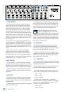
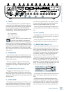
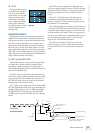
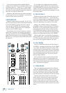
33. CONTROL ROOM SOURCE MATRIX
Typically, the engineer sends the main mix to an audi-
ence (if mixing live) or a mixdown deck (if recording).
But what if the engineer needs to hear something other
than the main mix? With the 1402-VLZ3, the engineer
has several choices of what to listen to. This is one of
those tricky parts, so buckle up.
Via these SOURCE switches, you can choose to listen
to any combination of main mix, ALT 3-4 and TAPE. By
now, you probably know what the main mix is. ALT 3-4 is
that additional stereo mix bus. Tape is the stereo signal
coming in from the TAPE INPUT [9] jacks.
Selections made in the source matrix deliver stereo
signals to the control room, phones and meter display.
With no switches engaged, there will be no signal at
these outputs and no meter indication.
The exception to that is the SOLO function. Regard-
less of the source matrix selection, engaging a channel’s
SOLO [24] switch will replace that selection with the
solo signal, also sent to the control room, phones and
meter. This is what makes the Level-Setting Procedure
so easy to do.
WARNING: Engaging both the TAPE and
ASSIGN TO MAIN MIX buttons in the
SOURCE matrix can create a feedback path
between TAPE INPUT and TAPE OUTPUT. Make sure
your tape deck is not in record, record-pause, or input
monitor mode when you engage these switches, or make
sure the CONTROL ROOM / SUBMIX [34] fader is fully
down.
Now you know how to select the signals to send to the
engineer’s control room or phones. From there, these
signals all pass through the same level control:
34. CONTROL ROOM/SUBMIX
This fader controls the levels of both the control room
outputs and phones outputs. The fader ranges from off,
through unity gain at the "U", to 10 dB of extra gain
when fully up.
When MAIN MIX is your control room source selec-
tion, those signals will now pass through two level con-
trols on the way to your control room amp and phones
— the MAIN MIX [32] faders and this CONTROL ROOM
/ SUBMIX fader. This way, you can send a nice healthy
level to the main output (MAIN MIX fader at “U”), and
a quiet level to the control room or phones (CONTROL
ROOM / SUBMIX fader wherever you like it).
When ALT 3-4 or TAPE is selected, or SOLO is en-
gaged, this fader will be the only one controlling these
levels (channel controls not withstanding).
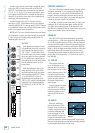
32. MAIN MIX FADERS
These faders control the levels of signals sent to the
main outputs: XLR [13], 1⁄4" TRS [11], and TAPE [10].
All channels and STEREO RETURNS that are not muted
or turned fully down will end up in the main mix.
Fully down is off, the "U" is unity gain, and fully up
provides 10 dB additional gain. This additional gain will
typically never be needed, but once again, it’s nice to
know it’s there. This is the fader to move down at the
end of the song when you want The Great Fade-Out.
32
33
34
35
36
37
38