


9
Owner’s Manual
Owner’s Manual
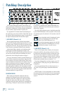
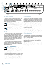
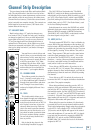
5. STEREO LINE INPUTS
(Channels 7–8, 9–10, 11–12 and 13–14)
These fully balanced inputs are designed for stereo or
mono, balanced or unbalanced signals, from –10 dBV to
+4 dBu. They can be used with just about any profes-
sional or semi-pro instrument, effect or tape player.
In the stereo audio world, an odd-numbered chan-
nel usually receives the “left signal.” For example, you
would feed the 1402-VLZ3’s line inputs 7-8 a stereo
signal by inserting the device’s left output plug into the
channel 7 jack, and its right output plug into the chan-
nel 8 jack.
When connecting a mono device (just one cord), al-
ways use the LEFT (MONO) input (jacks 7, 9, 11, or 13)
and plug nothing into the RIGHT input (jacks 8, 10, 12
or 14)— this way the signal will appear on both sides.
This trick is called “jack normalling.”
6. +4/–10 LEVEL (Stereo Channels only)
This switch adjusts the input sensitivity of the line
inputs on channels 7 to 14. If the sound source is a "–10"
device, engage this switch. If you are unsure, leave the
switch up, and perform the Level Setting Procedure,
substituting this switch for the GAIN knob to find the
best position for it.
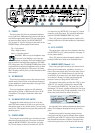
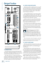
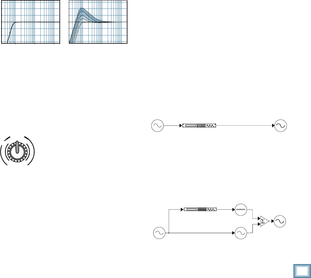
EFFECTS: SERIAL OR PARALLEL?
The next two sections toss the terms “serial” and
“parallel” around like hacky sacks. Here’s what we mean
by them:
“Serial” means that the entire signal is routed through
the effects device. Examples: compressor/limiters,
graphic equalizers. Line-level sources can be patched
through a serial effects device before or after the mixer,
or preferably through the insert jacks located on the
rear panel (CHANNEL INSERT [17] send/return).
“Parallel” means that a portion of the signal in the
mixer is tapped off to the device (AUX SEND), pro-
cessed and returned to the mixer (STEREO RETURN)
to be mixed with the original “dry” signal. This way,
multiple channels can all make use of the same effects
device. Examples: reverb, digital delay.
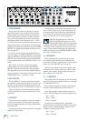
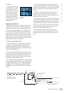
3. LOW CUT (Channels 1–6)
Each LOW CUT switch, often referred to as a High
Pass Filter (all depends on how you look at it), cuts bass
frequencies below 75 Hz at a rate of 18 dB per octave.
We recommend that you use LOW CUT on every
microphone application except kick drum, bass guitar,
or bassy synth patches. These aside, there isn’t much
down there that you want to hear, and filtering it out
makes the low stuff you do want much more crisp and
tasty. Not only that, but LOW CUT can help reduce the
possibility of feedback in live situations and it helps to
conserve the amplifier power.
Another way to consider LOW CUT’s function is that it
actually adds flexibility during live performances. With
the addition of LOW CUT, you can safely use LOW equal
-
ization on vocals. Many times, bass shelving EQ can
really benefit voices. Trouble is, adding LOW EQ also
boosts stage rumble, mic handling clunks and breath
pops. LOW CUT removes all those problems so you can
add low EQ without losing a woofer.
Here’s what the combination of LOW EQ and LOW
CUT looks like in terms of frequency curves:
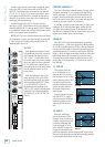
4. GAIN (Channels 1–6)
If you haven’t already, please read the Level-Setting
Procedure.
GAIN adjusts the input sensitivity of the mic and line
inputs connected to channels 1 through 6. This allows
signals from the outside world to be adjusted to optimal
internal operating levels.
If the signal originates through the
XLR jack, there will be 0 dB of gain
with the knob fully down, ramping to
60 dB of gain fully up.
Through the 1⁄4" input, there is 15
dB of attenuation fully down and 45 dB
of gain fully up, with a “U” (unity gain) mark at 10:00.
This 15 dB of attenuation can be very handy when you
are inserting a very hot signal, or when you want to add
a lot of EQ gain, or both. Without this “virtual pad,” this
scenario might lead to channel clipping.
Low Cut with Low EQ
20
Hz
100
Hz
1k
Hz
10k
Hz
20k
Hz
–15
–10
–5
0
+5
+10
+15
20
Hz
100
Hz
1k
Hz
10k
Hz
20k
Hz
–15
–10
–5
0
+5
+10
+15
Low Cut
Dry Signal
Processed
Signal
Insert
Send
Insert
Return
Dry Signal(s)
Dry Signal(s)
Aux
Send
Aux
Return
Wet Signal
Channel Path
Mix
Stage
Output
Section
Processed
Signal
Signal Processor
(e.g., Compressor)
Signal Processor
(e.g., Reverb)
Dry Signal
Processed
Signal
Insert
Send
Insert
Return
Dry Signal(s)
Dry Signal(s)
Aux
Send
Aux
Return
Wet Signal
Channel Path
Mix
Stage
Output
Section
Processed
Signal
Signal Processor
(e.g., Compressor)
Signal Processor
(e.g., Reverb)
M
I
C
G
A
I
N
0
U
60
-
1
0
d
B
V
+15dB -45dB
M
I
C
G
A
I
N
0
U
60
-
1
0
d
B
V
+15dB -45dB
M
I
C
G
A
I
N
0
U
60
-
1
0
d
B
V
+15dB -45dB
M
I
C
G
A
I
N
0
U
60
-
1
0
d
B
V
+15dB -45dB
M
I
C
G
A
I
N
0
U
60
-
1
0
d
B
V
+15dB -45dB
M
I
C
G
A
I
N
0
U
60
-
1
0
d
B
V
+15dB -45dB
U
OO
+10
U
OO
+20
U
OO
+20
U
O
O
+15
U
O
O
+15
U
O
O
+15
U
O
O
+15
U
O
O
+15
U
O
O
+15
U
O
O
+15
U
O
O
+15
U
O
O
+15
U
O
O
+15
U
O
O
+15
U
O
O
+15
U
O
O
+15
U
O
O
+15
U
O
O
+15
U
O
O
+15
U
O
O
+15
U
O
O
+15
U
O
O
+15
U
O
O
+15
U
+15-15
U
+15-15
U
+15
-15
U
+15-15
U
+15-15
U
+15
-15
U
+15-15
U
+15-15
U
+15
-15
U
+15-15
U
+15-15
U
+15
-15
U
+15-15
U
+15-15
U
+15
-15
U
+15-15
U
+15-15
U
+15
-15
U
+15-15
U
+15-15
U
+15
-15
U
+15-15
U
+15-15
U
+15
-15
U
+15-15
U
+15-15
U
+15
-15
U
+15-15
U
+15-15
U
+15
-15
dB
30
20
10
OO
40
50
5
5
U
60
10
dB
30
20
10
OO
40
50
5
5
U
60
10
dB
30
20
10
OO
40
50
5
5
U
60
10
dB
30
20
10
OO
40
50
5
5
U
60
10
dB
30
20
10
OO
40
50
5
5
U
60
10
dB
30
20
10
OO
40
50
5
5
U
60
10
dB
30
20
10
OO
40
50
5
5
U
60
10
dB
30
20
10
OO
40
50
5
5
U
60
10
dB
30
20
10
OO
40
50
5
5
U
60
10
dB
30
20
10
OO
40
50
5
5
U
60
10
dB
30
20
10
OO
40
50
5
5
U
60
10
dB
30
20
10
OO
40
50
5
5
U
60
10
MIC
2
MIC
3
MIC
4
MIC
5
MIC
6
BAL
OR
UNBAL
BAL
OR
UNBAL
BAL
OR
UNBAL
BAL
OR
UNBAL
BAL
OR
UNBAL
BAL
OR
UNBAL
AUX SEND
1
2
1
2
RIGHT
LEFT/
MONO
ALL BAL/UNBAL
BAL/UNBAL
L
R
LINE IN 1 LINE IN 2
LOW CUT
75 Hz
18dB/OCT
LOW CUT
75 Hz
18dB/OCT
LINE IN 3
LOW CUT
75 Hz
18dB/OCT
LINE IN 4
LOW CUT
75 Hz
18dB/OCT
LOW CUT
75 Hz
18dB/OCT
LINE IN 5 LINE IN 6
LOW CUT
75 Hz
18dB/OCT
GAINGAIN GAIN GAIN GAIN GAIN
LINE IN 7-8
LINE IN 9-10
LINE IN 11-12
LINE IN 13-14
AUX
HI
12kHz
MID
2.5kHz
LOW
80Hz
EQ
PAN
AUX
EQ
PAN
AUX
EQ
PAN
AUX
EQ
PAN
AUX
EQ
PAN
AUX
EQ
PAN
AUX
EQ
PAN
AUX
EQ
PAN
AUX
EQ
PAN
AUX
EQ
PAN
SOLO
1
MUTE
ALT 3
–
4 ALT 3
–
4 ALT 3
–
4 ALT 3
–
4 ALT 3
–
4 ALT 3
–
4 ALT 3
–
4 ALT 3
–
4 ALT 3
–
4
L R
HI
12kHz
MID
2.5kHz
LOW
80Hz
SOLO
2
MUTE
L R
HI
12kHz
MID
2.5kHz
LOW
80Hz
SOLO
3
MUTE
L R
HI
12kHz
MID
2.5kHz
LOW
80Hz
SOLO
4
MUTE
L R
HI
12kHz
MID
2.5kHz
LOW
80Hz
SOLO
5
MUTE
L R
HI
12kHz
MID
2.5kHz
LOW
80Hz
SOLO
6
MUTE
L R
HI
12kHz
MID
2.5kHz
LOW
80Hz
SOLO
7-8
MUTE
L R
HI
12kHz
MID
2.5kHz
LOW
80Hz
SOLO
9-10
MUTE
L R
HI
12kHz
MID
2.5kHz
LOW
80Hz
SOLO
11-12
MUTE
L R
HI
12kHz
MID
2.5kHz
LOW
80Hz
SOLO
13-14
MUTE
ALT 3
–
4
L R
L
MONO
MONO
MONO
MONO
R
BAL
OR
UNBAL
L
R
BAL
OR
UNBAL
L
R
BAL
OR
UNBAL
L
R
BAL
OR
UNBAL
TAPE
INPUT
TAPE
OUTPUT
L
R
L
R
20
10
7
4
2
0
2
4
7
10
20
30
LEVEL
SET
LEFT RIGHT
MAIN OUT
ALT 3–4
TAPE
MAIN MIX
ASSIGN
TO MAIN MIX
SOLO
MODE
LEVEL SET (PFL)
NORMAL (AFL)
C-R/SOURCE
PO48V WER
RUDE
SOLO
LIGHT
MAIN MIXCTL ROOM /SUBMIX
0dB=0dBu
LEVELLEVELLEVEL
-
10
LEVEL
+4
-
10
+4
-
10
+4
-
10
+4
MIC
1
X
D
R
M
I
C
P
R
E
X
D
R
M
I
C
P
R
E
X
D
R
M
I
C
P
R
E
X
D
R
M
I
C
P
R
E
X
D
R
M
I
C
P
R
E
X
D
R
M
I
C
P
R
E