


10
0dBu (.775 volts rms) at the rear output
jacks. The LM-3204’s main outputs are
0dBu=0dB Meter whether you are using
balanced or unbalanced cables.
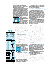
The meters are switched by the same circuits
that switch the Control Room and Phones moni-
tors. So whatever you are hearing in the monitors
is what’s on the meters. Normally, that would be
the main Left and Right bus outputs. If the Tape
Monitor switch is pushed down, the meters (and
the monitors) are connected to the Tape In jacks.
(See the Tape Monitor switch note in the Monitor-
ing section a little farther on.)
NOTE: The Control
Room fader does not affect
meter levels.
And remember, whenever
any solo button is pressed,
the meters are not reading the main output bus
level. When a Solo button is pressed, the moni-
tors and the meters are connected to the solo
buses for input level adjustment.
You should set your L/R levels for a reading in
the middle of the meters, with occasional peaks
reaching into the yellow +7 to +10 range. You
should never have the levels loud enough to light
the red OL LEDs, which are set at +20dBu, just
before clipping (+22dBu) to indicate
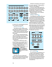
Return 3 control and circuitry.
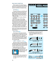
This allows you to use Alt 3–4 as a pair of
submix buses and then re-mix them back into
the main Left and Right buses.
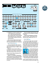
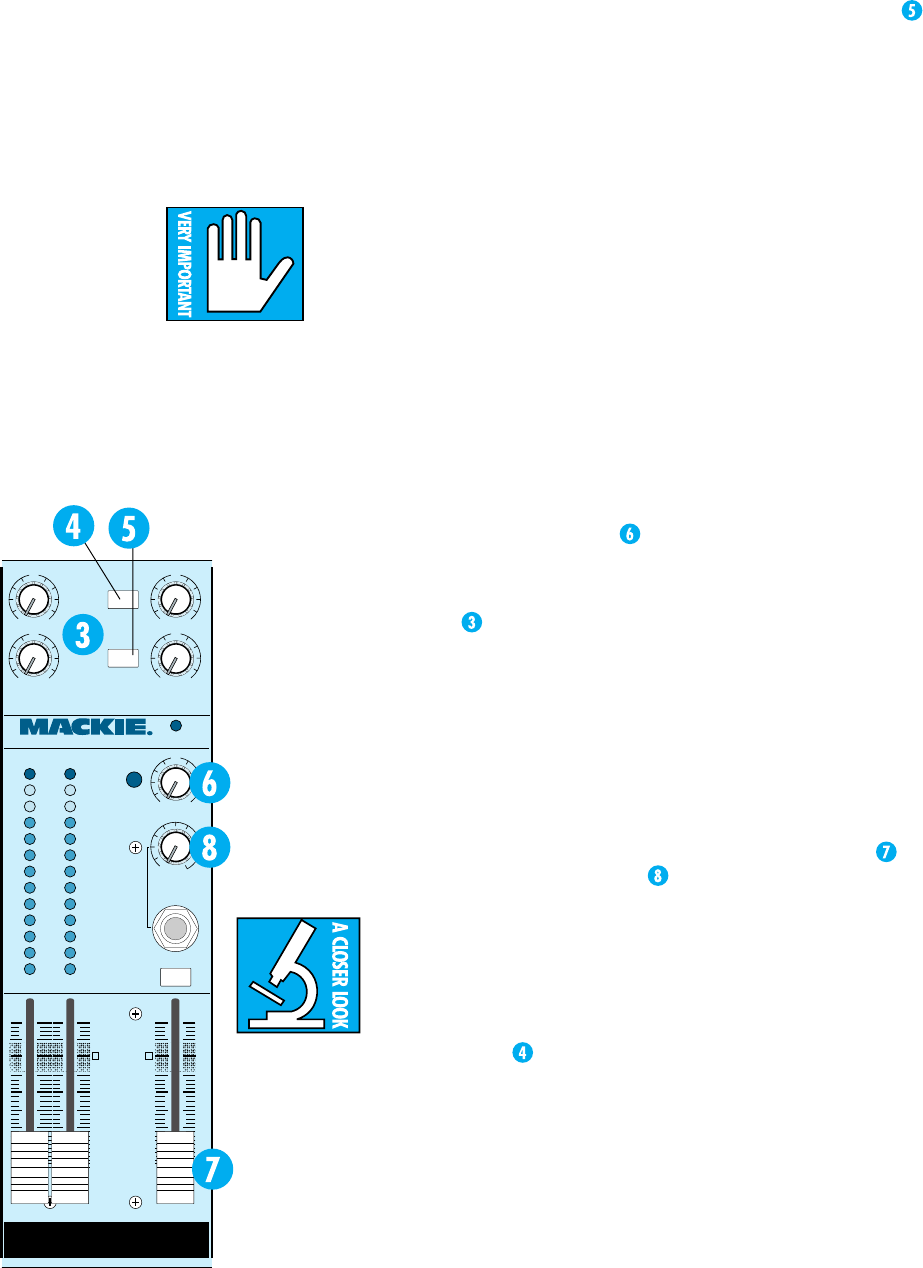
AUX RETURN TO CONTROL ROOM ONLY
It has such a long name that it hardly
needs any explanation. When this switch is
up, AUX Return 4 functions normally. When
the switch is down, the AUX Return 4 is dis-
connected from the main Left and Right buses
and is re-connected to the control room moni-
tor and headphone circuits (where it is mixed
back in with Left and Right signal on its way
to the Monitor section).
This allows you to use wet monitor, listen-
ing with echo or delay without actually using
the effect in the main Left and Right outputs,
or to “play along” to a cue or click feed with-
out having it go onto tape.
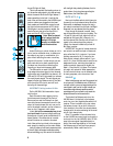
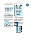
SOLO
When a Solo button is pressed, the soloed
signals are sent to the meters and the solo
buses, which are fed to the control room
monitor and headphone circuits. The Solo
control
in the main Output section sets
solo monitoring level. It has no effect on the
levels on the meters or on any of the main, al-
ternate or auxiliary buses.
Next to the Solo level control is the Rude
Solo Light, as nasty an indicator as our Indi-
cator Department could find without
actually being dangerous. When it is blink-
ing, something is soloed. Simplicity itself.
Furthermore, the –20 and OL LEDs on soloed
channel(s) glow steadily to indicate Solo-ed status.
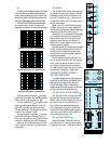
MONITORING
The LM-3204 has both Control Room
and Phone monitoring outputs, each cir-
cuit with its own level control. Monitoring
controls consist of the stereo Control Rm
fader, the Phones level control (with a handy
Phones jack just below it), and the Tape
Monitor switch.
Control Rm and Phone monitor outputs
always share the same sources:
• The main Left and Right buses under
normal conditions;
• The output of your tape recorder (or some
other source patched into the Tape In jacks)
when the Tape Monitor switch is pushed, or;
• The stereo solo buses whenever any Solo
switch is pressed. The solo circuits override
the Tape Monitor switch.
10
22
+20
OO
U
1
LEVEL
+20
OO
U
2
+20
OO
U
3
LEVEL
+20
OO
U
4
STEREO AUX RETURNS
AUX RETURN
TO CONTROL
ROOM ONLY
SOURCE
ALT 3-4
40
30
20
10
7
4
2
0
2
4
7
+
–
CLIP
PHONES
OO
SOLO
+20
OO
U
TAPE
MONITOR
LEVEL
POWER
LM-3204 STEREO LINE MIXER
dB
20
15
5
10
OO
5
10
30
40
U
dB
20
15
5
10
OO
5
10
30
40
U
LEFT RIGHT CONTROL R M
bus distortion.
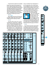
STEREO AUX RETURNS
The LM-3204 has 4 stereo Auxil-
iary (AUX) returns for reverb, delay
and other effect returns. The returns
pass through ganged stereo level con-
trols and are routed into the main
Left and Right buses. Each level con-
trol has a “U” detent and plenty of
gain (+20dB) for any effect you use.
Just like a channel strip input, any
return can be used in mono by patch-
ing into the Left input only.
There are a
couple of Mackie bo-
nus switches in the
AUX Return circuits:
THE SOURCE ALT 3–4 SWITCH
This switch works on the AUX
Return 3. With the switch up, AUX
Return 3 is just what it’s advertised
to be: an AUX Return. When the
Source Alt 3–4 switch is down, AUX
Return 3 inputs are disconnected.
Instead, the outputs of the Alt 3–4
buses are routed into the AUX