


13
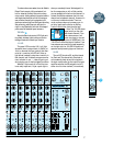
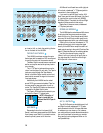
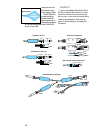
3. As a send-return insert for processing. Use a
1
⁄
4
" TRS (stereo) plug “Y”-ed to two mono
(TS)
1
⁄
4
" plugs. The tip should be wired to
send to the effect’s input, and the ring should
be wired as the return from the effect back
into the LM-3204. The sleeve is the common
ground connection.
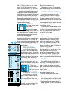
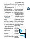
See the Insert Jack diagram at left. The same
diagram is on the back panel of the LM-3204 for
your wiring convenience. Bring your own flashlight.
MAIN/TAPE OUTPUTS
The Left and Right Main Outputs are each
electronically balanced, line level outputs, ca-
pable of driving line levels of –10dBV or +4dBu
equally well.
Each output jack is wired as a TRS (Tip-
Ring-Sleeve)
1
⁄
4
" phone jack. Like the balanced
input jacks, the tip of the jack is wired to the
“high” side of the input circuitry, the ring is
wired to the “low” side, and the sleeve is the
circuit ground connection.
Standard TS (Tip-Sleeve)
1
⁄
4
" phone plugs
may be connected to the LM-3204 Main Outputs
for connection to unbalanced equipment. The
sleeve of the TS plug will automatically connect
the low side of the jack to ground and unbalance
the output.
There is no change in signal level when using
an unbalanced (TS) cord instead of a balanced
(TRS) cord.
The Main Outputs also appear as unbalanced
outputs on the Tape L–R Out RCA jacks immedi-
ately to the right. (Also able to drive –10 to +4.)
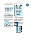
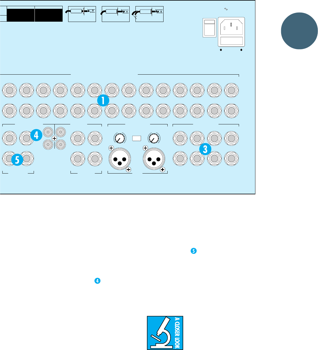
MAIN INSERTS
The main left and right output circuits also
have insert jacks available on the back panel.
Like the channel inserts, these jacks allow you to
tap the signal out of the circuit for processing in
another piece of equipment and then return the
processed audio back into the LM-3204. In this
case, the entire main left-right mixing buses will
be processed.
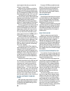
The main inserts occur just
after the bus summing amplifi-
ers and before the master Left
and Right faders. When “print-
ing” a mix, this would be the
place to patch in a stereo compressor/limiter, EQ
and/or aural exciter. If you’re using the LM-3204
for live sound, you may want to patch in a stereo
graphic equalizer or anti-feedback processor here.
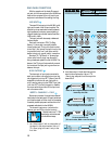
The main inserts are the same as the channel
inserts in regard to send/return, direct, and direct
with interrupt wiring. See the three ways to use
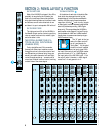
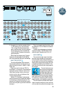
LAYOUT
AND
FUNCTION
FUSE INSIDE
SERIAL NUMBER MANUFACTURING DATE
POWER
120VAC
50/60 HZ 60W
1A/250V SLO BLO
ON
OFF
13 11 9 7
5
31
STEREO BALANCED OR UNBALANCED LINE INPUTS
CHANNEL INSERT OPTIONS
(MONO)
L
R
L
R
L
R
L
R
CHANNEL INSERTS
1
3
RL
MAIN INSERTS
21
MIC PREAMP
OUTPUT
MIC IN
RL
MAIN/TAPE OUTPUTS
RL
TAPE INPUTS
21
MIC PREAMP GAIN
10
dB
50
dB
G
A
I
N
G
A
I
N
PHANTOM
POWER
+48V
24
14 12 10 8 6 4
2
TIP OUT TO EFFECTS DEVICE
RING RETURN FROM EFFECTS
STEREO
PLUG
DIRECT OUT WITH
NO SIGNAL
INTERRUPTION
TO MASTER
DIRECT OUT WITH
SIGNAL
INTERRUPTION
TO MASTER
FOR USE AS AN
EFFECTS LOOP
(TIP = SEND,
RING = RETURN)
INSERT ALL THE WAY IN TO
THE "SECOND CLICK"
INSERT ONLY INTO THE
"FIRST CLICK"
MONO PLUG
MONO PLUG
10
dB
50
dB
CAUTION:
TO REDUCE THE
RISK OF FIRE, REPLACE WITH THE
SAME TYPE FUSE AND RATING
M
E TYPE.
F
USIBLE
N
OT
E
R.
E
RSONNEL.