


8
U
+30dB
OO
BALANCE
L
–15 +15
U
–12 +12
U
2
+15
OO
U
–15 +15
U
1
+15
OO
U
16
SHIFT
-20
OL
4
3
12k
STEREO
MONO
HI
80
LO
2.5k
MID
EQ
SOLO
AUX
LR
16
CHANNEL
MUTE
ALT 3-4
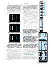
GAIN
GAIN
will also light that pulsating flambeau, that im-
pudent alarm, that ruby pharos guarding the
Mackie shore, the Rude Solo Light.
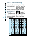
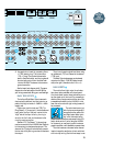
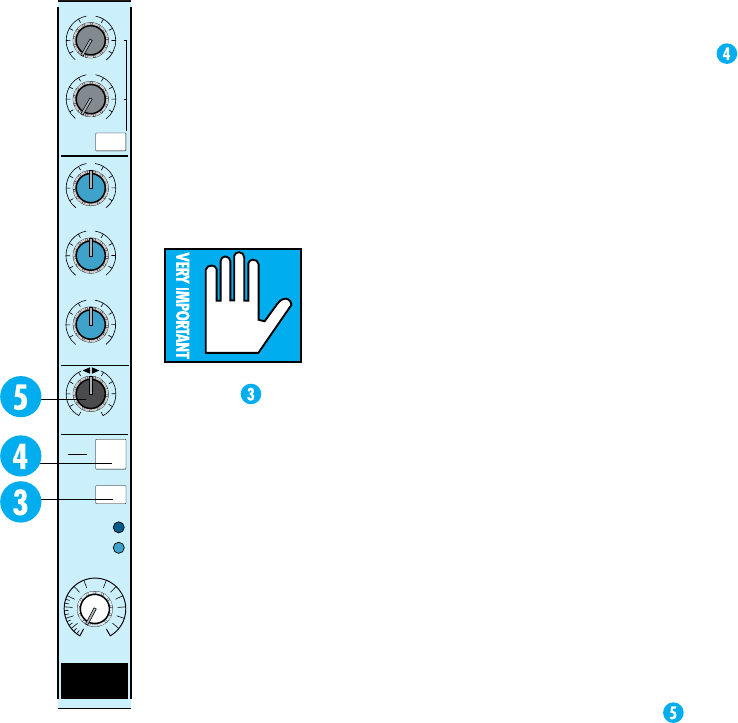
MUTE/ALT 3–4
Next up is the Mute switch, which lives up to
its name by muting its channel strip. When the
Mute switch is depressed, the signal in that in-
put module is removed from the main Left/Right
buses and from any selected Auxiliary buses.
Even though the channel is muted, there
can still be audio within the input module. The
–20 and OL lights will light, signal will still be
available at the Insert jack (channels 1–4),
and the channel Solo function will still work. In
regard to the main and auxiliary outputs,
though, the channel is effectively turned off.
But there is a twist.
IMPORTANT: Any and all muted channels
are routed to an additional pair of stereo out-
puts, called the Alt 3–4 outputs. If you have
nothing connected to Alt 3–4 outputs, the
Mute switch is simply a Mute switch. If you
use Alt 3–4, then the Mute switch acts like an
assignment button, switching the signal be-
tween two sets of stereo output buses: the
Main L–R and the Alt 3–4 buses. This feature
is fraught with potential. What appeared at
first as a two-bus mixer now is revealed to be,
for many purposes, a four-bus mixer. Yow!
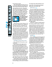
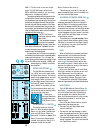
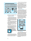
BALANCE
What looks like a pan pot, acts like a pan pot but
is not a pan pot? It’s a Balance control! With a ste-
reo input module, you are no longer dealing with a
mono signal to pan from left to right. Instead, you
have a stereo signal already spread across the
soundstage, and you may have to only tweak the
balance between the two channels a bit.
That’s what the Balance control on the
LM-3204 does. It’s identical to the balance
control on your Aunt Agatha’s Unrealistic hi-fi
receiver. There is a detent at the top, where
the balance is even. As you shift the control
from one side to the other, the stereo balance
changes, with the extremes being left channel
only or right channel only.
Note: It is possible to use a channel strip
on the LM-3204 as a mono input by plugging a
cord only into the Left (MONO) input. In this
case, the mono signal is applied equally to
both of the stereo signal paths. In this mode,
the Balance control acts just like a pan pot,
automatically! What a world we live in.
the red OL light will flash.
This is to be avoided. Overloading a mixer cir-
cuit forces the audio signal to clip and seriously
distort the sound. When the OL light flashes, it
means something is too loud. It could be the
level of the unit connected to the LM-3204 input
jacks or a device you plugged into the Insert
Jack; maybe you have the Gain control turned
too high or an extreme amount of EQ (which
lifts the gain in certain frequency ranges). You
need to find out what is too loud and turn it
down until the OL LED no longer lights.
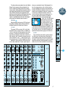
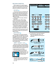
Note: When a channel
strip is soloed, both the
channel LEDs light
steadily to indicate that
module’s solo status.
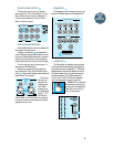
SOLO
A solo function on a mixer allows you to lis-
ten to (and on a Mackie mixer, to observe on
the meters) any input or combination of in-
puts without affecting the main or auxiliary
outputs of the mixer. In other words, you can
push a solo button to check something out
just about any time without affecting your
recording or sound reinforcement feed.
The Solo switch on each LM-3204 channel
strip assigns the stereo signal in that channel
to the stereo solo buses. Both the channel –20
LED and OL LED will light steadily to indicate
the module’s solo status. The solo signals are
tapped off after the Balance control, the Gain
control and the EQ circuits, and will be af-
fected by all these settings.
IMPORTANT!! Setting Levels with Solo
On the LM-3204, Solo has another impor-
tant function.
Each Solo switch also triggers circuitry
that disconnects the meters, the Control
Room monitors and the Phones from their
normal duties and reconnects them all to the
output of the solo buses. Not only can you lis-
ten to the soloed tracks but you can measure
them on the 13-segment main meters.
In fact, this is the recommended way to ad-
just input levels. As you are initially setting up
a stereo pair of inputs, push the Solo button. It
doesn’t matter if the channel strip is muted:
solo will function on a muted or unmuted
track. Now set the input level to the range you
want, simply by checking out the main meters.
Lastly, by means of extremely expensive state-
of-the-art highly obfuscated envelope-pushing
silicon technology, any Solo switch on the board