


7
LAYOUT
AND
FUNCTION
To make matters even easier, the crack Mackie
Detent Crew have put a little mechanical “pot-
hole” or detent at the Unity Gain point on every
rotary control. Adding detents is a precise, tedious
and largely thankless job, so think of those guys
every now and then as you’re going about your
glamorous and exciting lives mixing and recording
and performing, while they work late into the
night in rainy Woodinville with their little bags of
punches and elf-sized ball-peen hammers.
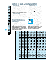
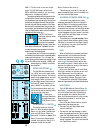
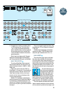
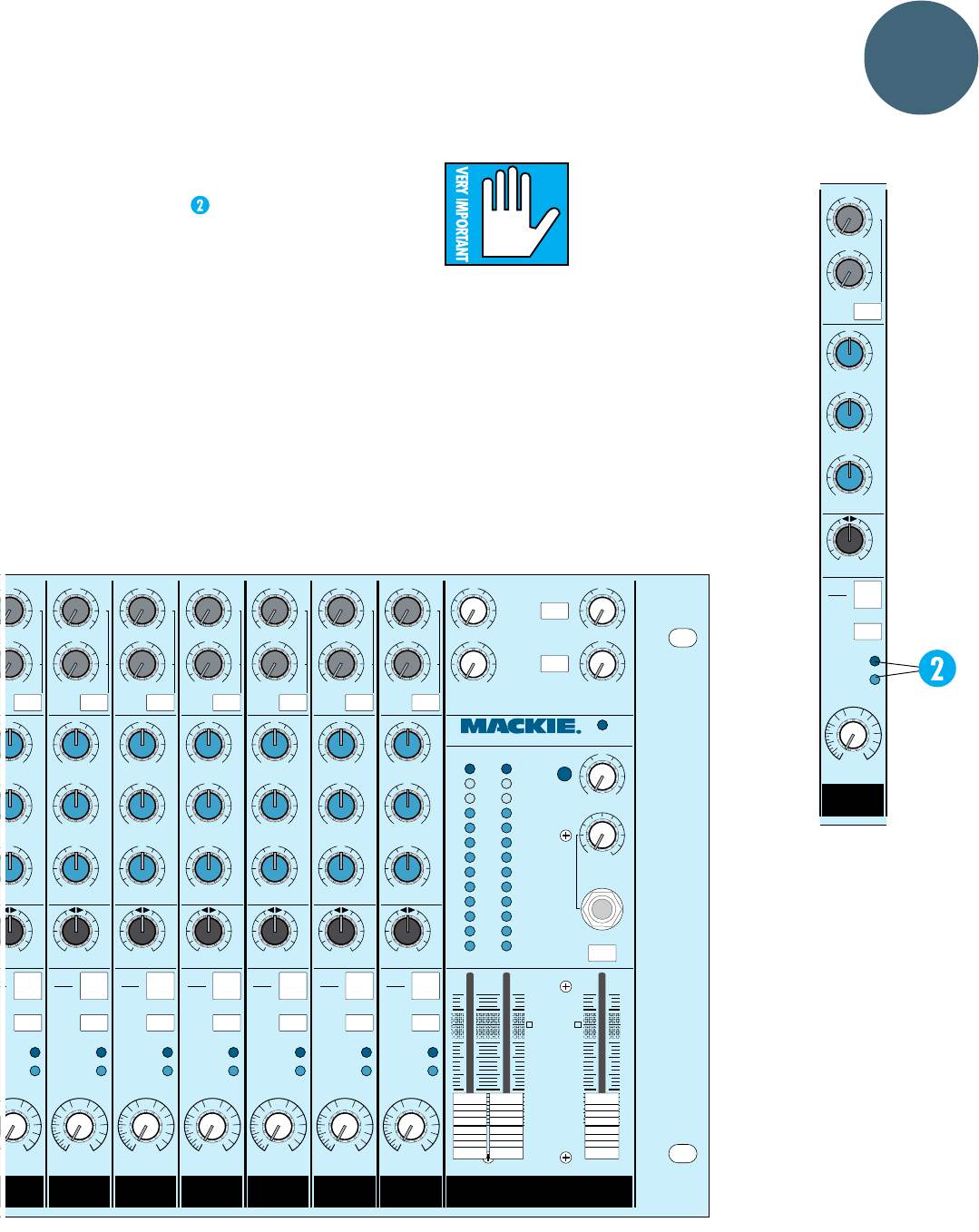
THE LEDs
Above the Gain knob are two LED (light-emit-
ting diode) indicator lights to help you monitor
the signal levels within each input module.
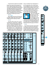
–20 LED
The green LED is marked –20. It will light
whenever there is a signal level of –20dBu (at
1kHz) or above at the input jacks of that chan-
nel strip. In practice, this LED will flicker or
light almost constantly when there is activity in
that channel, and it basically serves as a conve-
nient indicator for you — a way of figuring out
who’s singing now or what’s plugged into where.
Whether it lights rarely or is on all the time
is not really important; it’s just a porch light to
show you somebody’s home. We designed it to
be ultra-responsive, so, with a little practice,
you can probably tell what’s on the channel (or
at least the difference between the kick drum
channel and a keyboard channel). However, it’s
not the way to determine levels. There is a
much more accurate way to measure your in-
put strip levels: see the section on Setting
Levels in Solo further down the pike here.
Note: The –20 LED shows
signal activity on the right
side of each channel. If you
had a stereo source (two
cords, two plugs) or a mono
source (one plug into the left MONO jack), the
–20 LED will reflect that signal. However, if you
have a stereo source with no signal happening
on the right side, the –20 LED will be as unre-
sponsive as a hybernating hippo on Sominex
™
.
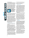
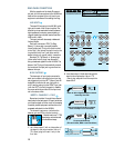
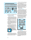
OL LED
The red LED is marked OL, and that stands
for OverLoad. The channel strip OverLoad cir-
cuits constantly check at two critical points in
the input module: after the line input’s first gain
amplifier and after the EQ and gain circuits. If
either circuit is driven too hard (into overload),
U
+30dB
OO
BALANCE
L
–15 +15
U
–12 +12
U
2
+15
OO
U
–15 +15
U
1
+15
OO
U
16
SHIFT
-20
OL
4
3
12k
STEREO
MONO
HI
80
LO
2.5k
MID
EQ
SOLO
AUX
LR
16
CHANNEL
MUTE
ALT 3-4
GAIN
GAIN
10
22
+20
OO
U
1
LEVEL
+20
OO
U
2
+20
OO
U
3
LEVEL
+20
OO
U
4
STEREO AUX RETURNS
AUX RETURN
TO CONTROL
ROOM ONLY
SOURCE
ALT 3-4
40
30
20
10
7
4
2
0
2
4
7
+
–
CLIP
PHONES
OO
SOLO
+20
OO
U
TAPE
MONITOR
LEVEL
POWER
LM-3204 STEREO LINE MIXER
dB
20
15
5
10
OO
5
10
30
40
U
dB
20
15
5
10
OO
5
10
30
40
U
LEFT RIGHT CONTROL R M
U
+30dB
A
LANCE
+15
U
+12
U
+15
O
U
1
5+15
U
+15
U
10
SHIFT
-20
OL
4
3
12k
HI
80
LO
2.5k
MID
EQ
L
O
U
X
R
U
+30dB
OO
BALANCE
L
–15 +15
U
–12 +12
U
2
+15
OO
U
–15 +15
U
1
+15
OO
U
11
SHIFT
-20
OL
4
3
12k
STEREO
MONO
HI
80
LO
2.5k
MID
EQ
SOLO
AUX
LR
U
+30dB
OO
BALANCE
L
–15 +15
U
–12 +12
U
2
+15
OO
U
–15 +15
U
1
+15
OO
U
12
SHIFT
-20
OL
4
3
12k
STEREO
MONO
HI
80
LO
2.5k
MID
EQ
SOLO
AUX
LR
U
+30dB
OO
BALANCE
L
–15 +15
U
–12 +12
U
2
+15
OO
U
–15 +15
U
1
+15
OO
U
13
SHIFT
-20
OL
4
3
12k
STEREO
MONO
HI
80
LO
2.5k
MID
EQ
SOLO
AUX
LR
U
+30dB
OO
BALANCE
L
–15 +15
U
–12 +12
U
2
+15
OO
U
–15 +15
U
1
+15
OO
U
14
SHIFT
-20
OL
4
3
12k
STEREO
MONO
HI
80
LO
2.5k
MID
EQ
SOLO
AUX
LR
U
+30dB
OO
BALANCE
L
–15 +15
U
–12 +12
U
2
+15
OO
U
–15 +15
U
1
+15
OO
U
15
SHIFT
-20
OL
4
3
12k
STEREO
MONO
HI
80
LO
2.5k
MID
EQ
SOLO
AUX
LR
U
+30dB
OO
BALANCE
L
–15 +15
U
–12 +12
U
2
+15
OO
U
–15 +15
U
1
+15
OO
U
16
SHIFT
-20
OL
4
3
12k
STEREO
MONO
HI
80
LO
2.5k
MID
EQ
SOLO
AUX
LR
1
0
A
NNEL
11
CHANNEL
12
CHANNEL
13
CHANNEL
14
CHANNEL
15
CHANNEL
16
CHANNEL
T
E
3
-4
MUTE
ALT 3-4
MUTE
ALT 3-4
MUTE
ALT 3-4
MUTE
ALT 3-4
MUTE
ALT 3-4
MUTE
ALT 3-4
GAINGAINGAINGAINGAINGAINGAIN