


1
ONYX 4•Bus
ONYX 4•Bus
down to the lowest note you ever heard. “Peaking” means
that the frequencies around the center frequency are
less affected by the EQ the further away they are.
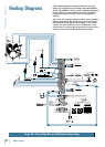
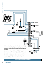
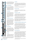
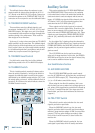
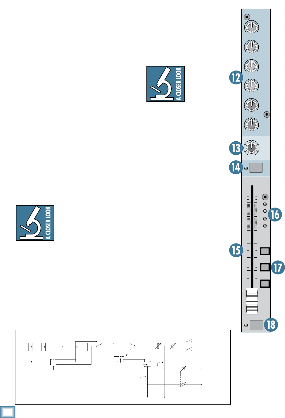
1. AUX Sends
These tap a portion of each channel’s signal (pre or
post-fader) out to either an effects processor (post-fader)
or for stage monitoring (pre-fader). The AUX Send lev-
els are controlled by the channel’s AUX 1-6 knobs, and
by the AUX SEND MASTERS knobs [55].
These are more than just effects and monitor sends.
They can be used to create stereo in-ear monitor mixes,
generate separate mixes for recording, for another zone,
or “mix-minuses” for broadcast.
1. PAN
PAN adjusts the amount of channel signal sent to the left
versus the right outputs
.
With the PAN knob hard left, the signal feeds the
MAIN LEFT (and GROUP 1 and 3, depending on the
setting of the GROUP ASSIGN switches). With the knob
hard right, the signal feeds the MAIN RIGHT (and
GROUP 2 and 4).
Constant Loudness
The Onyx 4•Bus PAN control em-
ploys a design called “Constant Loud-
ness.” If you have a channel panned
hard left (or right) and then pan to
the center, the signal is attenuated
3 dB to maintain the same apparent
loudness. Otherwise, it would make the sound appear
much louder when panned center.
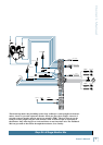
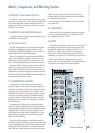
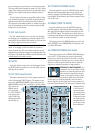
14. MUTE
Press this switch to mute the individual channel. This
disconnects the channel’s signal from all the Groups,
the Main Mix, and Aux Send buses (pre* and post-
fader). You can still solo the channel (PFL) when the
MUTE switch is pushed in.
* If the pre-fader Aux Send’s internal jumper is wired for pre-Mute
[56], the MUTE switch will not affect the PRE Aux Send.
15. Channel Fader
The fader controls the channel’s
level…from off to unity gain at the
“U” marking, on up to 10 dB of ad-
ditional gain.
“U” Like Unity Gain
Mackie mixers
have a “U” symbol
on many of the
level controls.
This “U” stands
for “unity gain,”
meaning no change in signal level.
Once you have adjusted the input
signal to line-level, you can set the
controls at “U” and your signals will
travel through the mixer at opti-
mal levels. What’s more, many of
the labels on our level controls are
measured in decibels (dB), so you’ll
know what you’re doing level-wise
if you choose to change a control’s
settings.
16. Signal Level LEDs
These LEDs indicate the channel’s
signal level after the GAIN and
EQ controls, but just prior to the
channel’s
fader. So even if the fader
is turned down, you can see if a
signal is present.
If you’ve followed the “Set the Lev-
els”
procedure, the –20 and 0 LEDs
should light frequently, the +10
LED should light occasionally, and
the OL (Overload) LED should not
light at all. If the OL LED is blink-
ing frequently, the signal is probably
distorted from overdriving the input.
Either turn down the GAIN control
or turn down the signal at its source.
10
dB
30
20
10
O O
40
5
5
U
60
50
AUX
1
GAIN
+
40dB
U
-
20dB
U
20
30
40
60
OUT
IN
EQ
LOW
80 Hz
HIGH
12kHz
LOW
MID
HIGH
MID
U
+15
-
15
U
+15
-
15
U
+15
-
15
U
+15
-
15
FREQ
2k
8k 400
FREQ
400
2k 1 00
4
3
2
1
5
6
O O
MAX
O O
MAX
O O
MAX
O O
MAX
O O
MAX
O O
MAX
L
R
PAN
1
OL
+
10
0
-
20
ASSIGN
MAIN
MIX
1
-
2
3
-
4
PAD
48V 48V
EQ
MUTE
PFL
'!). ).3%24,/7#54 %1
%1
)./54
-54%
&!$%2
0!.
!33)'.
!583%.$
+./"
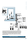
0/34
3)'.!,
02%3)'.!,
4/!583%.$3
).4%2.!,*5-0%2
).4%2.!,
*5-0%2
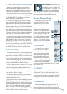
!UX0REVS0OST
3IGNAL&LOW$IAGRAM
0/34
-54%
02%-54%
02%%1
02%%1
0/34
%1
0/34%1
).054
$)2%#4
/54
4/!583%.$
"530/34&!$%2
4/!583%.$
"5302%&!$%2