4
ONYX 4•Bus
ONYX 4•Bus
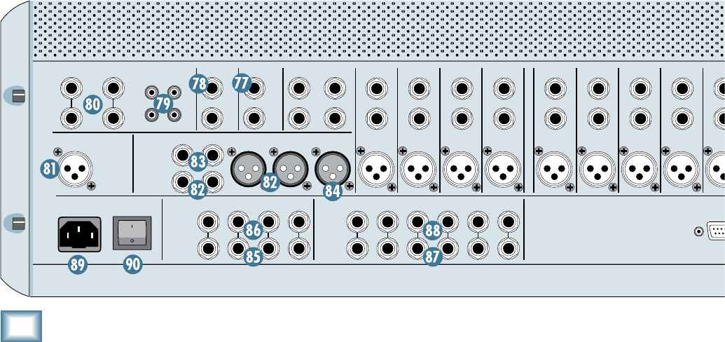
8. MAIN INSERTS
These 1/4" TRS jacks are for connecting serial effects
such as compressors, equalizers, deessers, or filters.
The insert point is after the mix amps and BREAK [61]
switch, but before the MAIN MIX faders and the built-in
compressor. Refer to the description of the channel insert
on the previous page to see how to make this connection.
84. MONO OUT
This male XLR output connector provides a balanced
line-level signal that is a combination of the left and right
MAIN OUT signals (L+R). You can use this for a separate
mix that doesn’t require a stereo feed, or to simply test
the monaural compatibility of your stereo mix.
85. GROUP OUTS 1-4
These 1/4
"
TRS output connectors provide balanced
or unbalanced line-level signals for connecting to the
inputs of any line-level device.
86. GROUP SEND INSERTS
These 1/4
"
TRS jacks are for connecting serial effects
such as compressors, equalizers, deessers, or filters. The
insert point is after the mix amps, but before the Group
Send Masters (and before the built-in stereo compres-
sor). Refer to the description of the channel insert
on
the previous page to see how to make this connection.
87. AUX SENDS 1-6
These 1/4
"
TRS output connectors provide balanced
or unbalanced line-level signals for connecting to the
inputs of effects devices or stage monitor amplifiers.
CAUTION
INSERT
1
INSERT
2
INSERT
3
INSERT
4
INSERT
5
INSERT
6
INSERT
7
INSERT
8
INSERT
9
INSERT
10
INSERT
11
INSERT
12
INSERT
13
INSERT
14
INSERT
15
INSERT
16
INSERT
17
INSERT
18
INSERT
19
INSERTINSERTINSERTINSERTINSERTINSERTINSERTINSERTINSERT
20
MTRX OUT
POWER
ON
B
A
MON OUT
R
L
29
30
31
32
R
L
R
L
LINE
LINE IN LINE IN
BAL/UNBAL
BAL/UNBALBAL/UNBAL
BAL/UNBAL
BAL/UNBAL BAL/UNBAL
BAL/UNBAL
MONOMONO
BAL/UNBAL
O
N
Y
X
M
I
C
P
R
E
O
N
Y
X
M
I
C
P
R
E
O
N
Y
X
M
I
C
P
R
E
O
N
Y
X
M
I
C
P
R
E
O
N
Y
X
M
I
C
P
R
E
O
N
Y
X
M
I
C
P
R
E
O
N
Y
X
M
I
C
P
R
E
O
N
Y
X
M
I
C
P
R
E
O
N
Y
X
M
I
C
P
R
E
MIC
21
LINE
BAL/UNBAL
MIC
LINE
BAL/UNBAL
O
N
Y
X
M
I
C
P
R
E
MIC
LINE
BAL/UNBAL
O
N
Y
X
M
I
C
P
R
E
MIC
LINE
BAL/UNBAL
O
N
Y
X
M
I
C
P
R
E
MIC
LINE
BAL/UNBAL
O
N
Y
X
M
I
C
P
R
E
MIC
LINE
BAL/UNBAL
O
N
Y
X
M
I
C
P
R
E
MIC
LINE
BAL/UNBAL
O
N
Y
X
M
I
C
P
R
E
MIC
LINE
BAL/UNBAL
O
N
Y
X
M
I
C
P
R
E
MIC
LINE
BAL/UNBAL
O
N
Y
X
M
I
C
P
R
E
MIC
LINE
BAL/UNBAL
O
N
Y
X
M
I
C
P
R
E
MIC
LINE
BAL/UNBAL
O
N
Y
X
M
I
C
P
R
E
MIC
LINE
BAL/UNBAL
O
N
Y
X
M
I
C
P
R
E
MIC
O
N
Y
X
M
I
C
P
R
E
MIC
O
N
Y
X
M
I
C
P
R
E
MIC
O
N
Y
X
M
I
C
P
R
E
MIC
O
N
Y
X
M
I
C
P
R
E
MIC
O
N
Y
X
M
I
C
P
R
E
MIC
LINE
BAL/UNBAL
O
N
Y
X
M
I
C
P
R
E
MIC
LINE
BAL/UNBAL
LINE
BAL/UNBAL
LINE
BAL/UNBAL
LINE
BAL/UNBAL
LINE
BAL/UNBAL
LINE
BAL/UNBAL
O
N
Y
X
M
I
C
P
R
E
MIC
LINE
BAL/UNBAL
O
N
Y
X
M
I
C
P
R
E
MIC
4 3 2 1 6 5 4 3 2 1
RIGHT
2
1
TAPE
TALK BACK
MIC
22
LINE
BAL/UNBAL
MIC
23
LINE
BAL/UNBAL
MIC
24
LINE
BAL/UNBAL
MIC
25
LINE
BAL/UNBAL
MIC
26
LINE
BAL/UNBAL
MIC
27
LINE
BAL/UNBAL
MIC
28
LINE
BAL/UNBAL
MIC
GROUP
INSERTS
GROUP
OUTS
AUX
INSERTS
AUX
SENDS
MAIN
OUTS
MAIN
INSERTS
RIGHT LEFT
MAIN BALANCED OUTS
RIGHT LEFT MONO
OUTIN
OUTIN
R
L
R
L
STEREO RETURNS
DIRECT OUTS
POST GAIN / INSERT
(BALANCED) (BALANCED) (BALANCED)
1
-
8
9-16
17
-
24
(BALANCED)
25
-
32
LEFT
(MONO)
88. AUX SEND INSERTS
These 1/4
"
TRS jacks are for connecting serial effects
such as compressors, equalizers, deessers, or filters.
The insert point is after the mix amps, but before the
Aux Send Masters and the AFL Solo switch (so you can
hear the external processor when soloing the aux send).
Refer to the description of the channel insert
on page 22
to see how to make this connection.
8. Power Receptacle
This is a standard 3-prong IEC power connector. Con-
nect the detachable linecord (included in the box with
your Onyx 4•Bus) to the power receptacle, and plug the
other end of the linecord into an AC outlet. The Onyx
4•Bus has a universal power supply that can accept
any AC voltage ranging from 100 VAC to 240 VAC. No
need for voltage select switches. It will work virtually
anywhere in the world. That’s why we call it a “Planet-
Earth” power supply! This also means that it is less
susceptible to voltage sags or spikes, providing greater
electromagnetic isolation and better protection against
AC line noise.
0. POWER Switch
This one is self-explanatory. When the POWER switch
is turned ON, power is supplied to the Onyx 4•Bus and
the POWER LED on the front panel lights up.
Press the bottom of this switch to put the mixer into
standby mode. It will not function, but the circuits are still
live. To remove AC power, either turn off the AC mains sup-
ply, or unplug the power cord from the mixer and the AC
mains supply.


