


1
Owner’s Manual
Owner’s Manual
71. AFL Solo Switch
The AFL switch allows you to hear the Group signal
through your headphones or monitor outputs. This
comes after the Group Fader and before the MUTE
switch, so you can hear the relative signal level on each
Group even when they are muted.
When you engage the AFL switch on two consecu-
tive odd/even Groups (i.e., 1 and 2, 3 and 4), the soloed
signal appears in stereo in the headphones and monitor
outputs. This is useful when you are using a pair of Group
Sends in stereo to feed an in-ear monitoring system.
Remember, PFL solo mode always overrides AFL solo
mode. If you engage a PFL solo switch on a mono or
stereo channel, the AFL solo is disconnected from the
headphones and monitor outputs and replaced with the
PFL signal. The Rude Solo LEDS below the SOLO meters
indicate which solo mode is active.
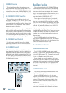
7. MAIN MIX Fader
This is the master fader that control the levels at the
MAIN OUTS.
When MAIN TO MON [51] is selected in the PHONES/
MONITOR Section, the MAIN MIX fader also controls the
main mix level in the PHONES and MONITOR outputs
[46/78].
When the fader is fully down, the MAIN MIX is off.
The “U” marking indicates unity gain, and fully up pro-
vides 10 dB of additional gain. Typically, this fader is set
near the “U” label and left alone, but it can be used for
song fade-outs or quick system-wide mutes.
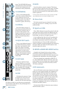
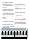
Rear Panel
This is where all the connections are made to the
Onyx 4•Bus (except the headphones and lamps).
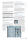
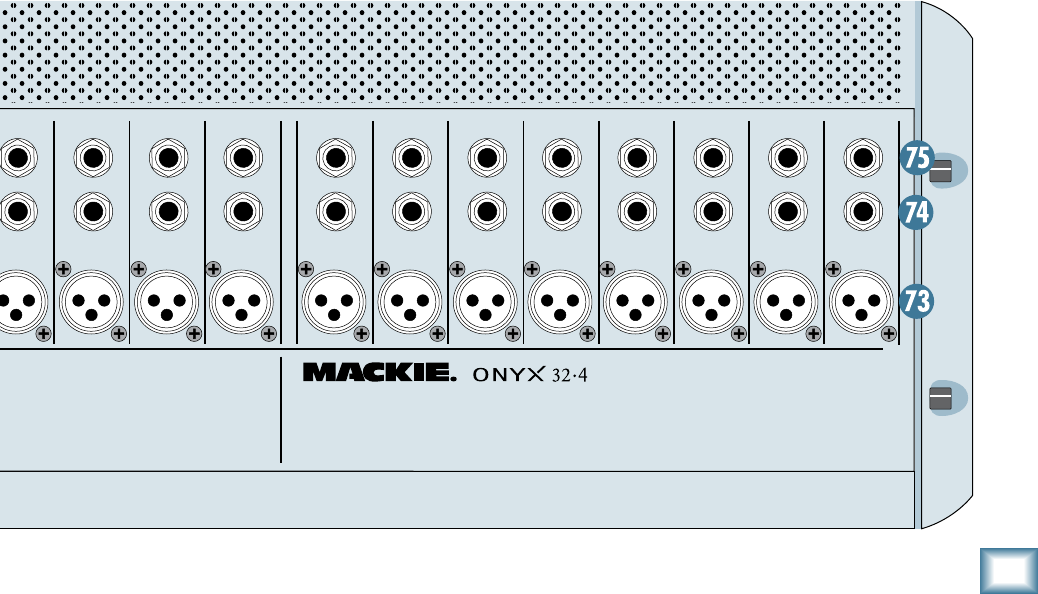
7. MIC Input
This is a female XLR connector, which accepts a bal-
anced microphone input from almost any type of micro-
phone. The microphone preamps feature our new Onyx
design, with higher fidelity and headroom rivaling any
standalone mic preamp on the market today.
The XLR inputs are wired as follows:
Pin 1 = Shield or ground
Pin 2 = Positive (+ or hot)
Pin 3 = Negative (– or cold)
The MIC inputs can accept a balanced line-level input
when the PAD [1] switch on the channel strip is pushed
in (the input impedance is lower than the LINE input).
74. LINE Input
This is a 1/4" TRS connector, which accepts a balanced or
unbalanced line-level input signal from almost any source.
When connecting a balanced signal to the LINE inputs,
wire them as follows:
Tip = Positive (+ or hot)
Ring = Negative (– or cold)
Sleeve = Shield or ground
When connecting an unbalanced signal, wire them as
follows:
Tip = Positive (+ or hot)
Sleeve = Shield or ground
CAUTION
INSERT
1
INSERT
2
INSERT
3
INSERT
4
INSERT
5
INSERT
6
INSERT
7
INSERT
8
INSERT
9
INSERT
10
INSERT
11
INSERT
12
INSERT
13
INSERT
14
INSERT
15
INSERT
16
INSERT
17
INSERT
18
INSERT
19
INSERTINSERTINSERTINSERTINSERTINSERTINSERTINSERTINSERT
20
MTRX OUT
POWER
ON
B
A
MON OUT
R
L
29
30
31
32
R
L
R
L
LINE
LINE IN LINE IN
BAL/UNBAL
BAL/UNBALBAL/UNBAL
BAL/UNBAL
BAL/UNBAL BAL/UNBAL
BAL/UNBAL
MONOMONO
BAL/UNBAL
O
N
Y
X
M
I
C
P
R
E
O
N
Y
X
M
I
C
P
R
E
O
N
Y
X
M
I
C
P
R
E
O
N
Y
X
M
I
C
P
R
E
O
N
Y
X
M
I
C
P
R
E
O
N
Y
X
M
I
C
P
R
E
O
N
Y
X
M
I
C
P
R
E
O
N
Y
X
M
I
C
P
R
E
O
N
Y
X
M
I
C
P
R
E
MIC
21
LINE
BAL/UNBAL
MIC
LINE
BAL/UNBAL
O
N
Y
X
M
I
C
P
R
E
MIC
LINE
BAL/UNBAL
O
N
Y
X
M
I
C
P
R
E
MIC
LINE
BAL/UNBAL
O
N
Y
X
M
I
C
P
R
E
MIC
LINE
BAL/UNBAL
O
N
Y
X
M
I
C
P
R
E
MIC
LINE
BAL/UNBAL
O
N
Y
X
M
I
C
P
R
E
MIC
LINE
BAL/UNBAL
O
N
Y
X
M
I
C
P
R
E
MIC
LINE
BAL/UNBAL
O
N
Y
X
M
I
C
P
R
E
MIC
LINE
BAL/UNBAL
O
N
Y
X
M
I
C
P
R
E
MIC
LINE
BAL/UNBAL
O
N
Y
X
M
I
C
P
R
E
MIC
LINE
BAL/UNBAL
O
N
Y
X
M
I
C
P
R
E
MIC
LINE
BAL/UNBAL
O
N
Y
X
M
I
C
P
R
E
MIC
O
N
Y
X
M
I
C
P
R
E
MIC
O
N
Y
X
M
I
C
P
R
E
MIC
O
N
Y
X
M
I
C
P
R
E
MIC
O
N
Y
X
M
I
C
P
R
E
MIC
O
N
Y
X
M
I
C
P
R
E
MIC
LINE
BAL/UNBAL
O
N
Y
X
M
I
C
P
R
E
MIC
LINE
BAL/UNBAL
LINE
BAL/UNBAL
LINE
BAL/UNBAL
LINE
BAL/UNBAL
LINE
BAL/UNBAL
LINE
BAL/UNBAL
O
N
Y
X
M
I
C
P
R
E
MIC
LINE
BAL/UNBAL
O
N
Y
X
M
I
C
P
R
E
MIC
4 3 2 1 6 5 4 3 2 1
RIGHT
2
1
TAPE
TALK BACK
MIC
22
LINE
BAL/UNBAL
MIC
23
LINE
BAL/UNBAL
MIC
24
LINE
BAL/UNBAL
MIC
25
LINE
BAL/UNBAL
MIC
26
LINE
BAL/UNBAL
MIC
27
LINE
BAL/UNBAL
MIC
28
LINE
BAL/UNBAL
MIC
GROUP
INSERTS
GROUP
OUTS
AUX
INSERTS
AUX
SENDS
MAIN
OUTS
MAIN
INSERTS
RIGHT LEFT
MAIN BALANCED OUTS
RIGHT LEFT MONO
OUTIN
OUTIN
R
L
R
L
STEREO RETURNS
DIRECT OUTS
POST GAIN / INSERT
(BALANCED) (BALANCED) (BALANCED)
1
-
8
9-16
17
-
24
(BALANCED)
25
-
32
LEFT
(MONO)