


16
ONYX 4•Bus
ONYX 4•Bus
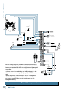
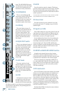
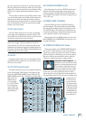
8. COMP ASSIGN
Use this switch to assign the compressor to either the
MAIN MIX, GROUP 1-2, GROUP 3-4, or OFF (not assigned).
When the compressor is assigned to the MAIN MIX, it
is inserted in the signal flow after the MAIN MIX fader,
so it works as an external dynamics processor. Once the
signal crosses the THRESHOLD, boosting the MAIN MIX
fader results in little change in the output level (de-
pending on the RATIO setting).
When the compressor is assigned to one of the GROUP
pairs, it is inserted in the signal flow before the GROUP
faders. In this way, the compressor can act on a group of
channels assigned to the subgroup (for example, drum
microphones), and the overall level of the compressed
group can be mixed into the main mix.
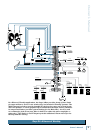
. FAST ATTACK
The ATTACK setting determines how fast the com-
pressor reacts once the threshold has been exceeded. It
also affects the release time, which determines how fast
the compressor turns off once the signal falls below the
threshold.
With the switch up, the attack and release times are
calibrated to respond to the overall signal level without
the audible “pumping” and “breathing” artifacts that are
sometimes associated with compressors. In
most cases, this is the setting you would use
for live sound and recording applications.
There may be some situtations that
require a faster acting attack and release.
For example, mic’ing a snare drum produces
some fast transient peaks that may get
through the compressor before it can act
on the signal. Pushing in the FAST ATTACK
switch allows the compressor to react much
faster on quick transient peaks and release
the compression quickly between the peaks.
You can experiment with both settings to
determine which one works best in your
application.
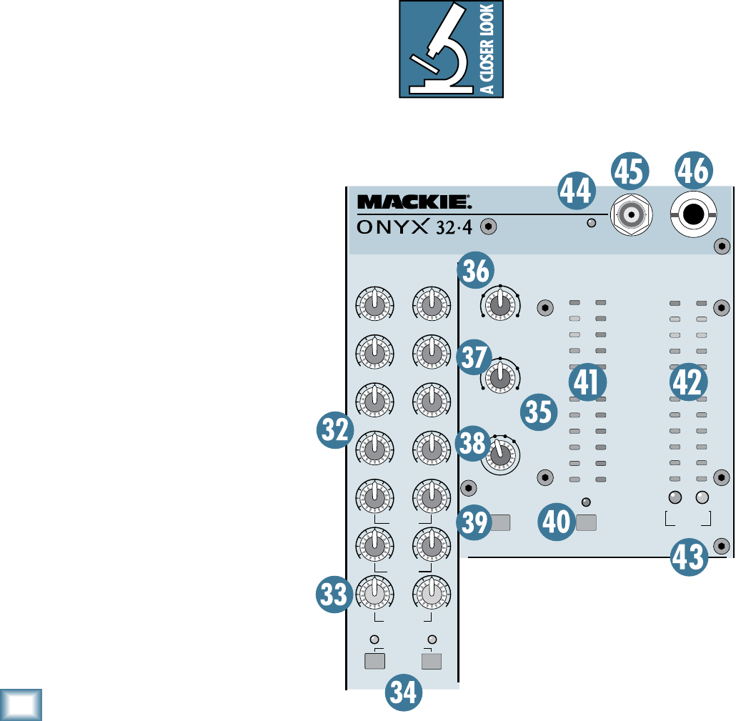
40. BYPASS COMP Switch
When the BYPASS COMP switch is pushed
in, the signal bypasses the compressor, but
still allows you to see the input signal level
to the compressor and the amount of gain
reduction applied to the signal on the me-
ters. This is useful when setting up the com-
pressor settings prior to actually engaging
the compressor in a live sound application,
and for making A/B comparisons between
the compressed and uncompressed sound.
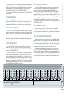
41. COMPRESSOR Meters
The INPUT meter indicates the signal level at the
input of the compressor. Use this to help determine the
setting of the THRESHOLD control. Once the input level
crosses the threshold setting, the G.R. (Gain Reduction)
meters begin to light (top to bottom), as they indicate
how much gain reduction is being applied to the signal.
Note: If the COMP ASSIGN switch [38] is OFF, the
COMPRESSOR meters will not indicate any signal.
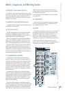
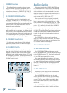
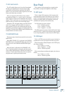
4. LEFT/RIGHT Level Meters
The Onyx 4•Bus Left and Right Level meters are
made up of two columns of twelve LEDs, with three
colors to indicate different ranges of signal level, traffic
light style. They range from –30 at the bottom, to 0 in
the middle, to +20 (CLIP) at the top.
The 0 LED in the middle is labeled 0 dB = 0 dBu.
You may already be an expert at the
world of “+4” (+4 dBu=1.23 V) and
“–10” (–10 dBV=0.32 V) operating
levels. What makes a mixer one or
the other is the relative 0 dB VU (or
0 VU) chosen for the meters. A “+4”
mixer, with +4 dBu pouring out the back will actually
read 0 VU on its meters. A “–10” mixer, with a –10 dBV
RUDE
SOLO
PFL AFL
PHONES
12V, 0.5A
LAMP
POWER
PREMIUM ANALOG MIXER
w/ PERK INS E Q
MONITOR
MAIN MIX
OO
MAX
OO
MAX
OO
MAX
OO
MAX
OO
MAX
OO
MAX
20
15
10
6
3
0
2
4
7
10
20
30
LEFT RIGHT
0dB=0dBu
LEVEL
SET
CLIP
CLIP
COMPRESSOR
MATRIX
A
1
2
3
4
LEFT
RIGHT
OO
+15
OO
MAX
OO
MAX
OO
MAX
OO
MAX
OO
MAX
OO
MAX
OO
+15
MASTER
B
PHONES
OO
MAX
OO
MAX
OO
MAX
OO
MAX
SOLO LEVEL
TB ASSIGN
STEREO
MAIN
TO MON
FAST
ATTACK
BYPASS
COMP
20
15
10
6
3
0
2
4
7
10
20
30
1
2
3
4
5
6
7
8
9
10
12
15
INPUT G.R.
0dB=0dBu
AUX
1-2
AUX
3-4
AUX
5-6
MAIN
MIX
AFL AFL
COMP
ASSIGN
GRP
GRP
GRP
GRP
MONO
TALKBACK
OO
MAX
5:11.5:1
2:1
MAI
N
MI
X
OF
F
GR
P
3-
4
GR
P
1-
2
THRESHOLD
+10
0
-10
-20
-30
LIMITOFF
RATIO