


16
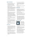
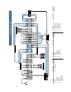
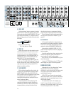
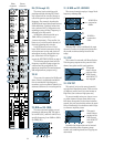
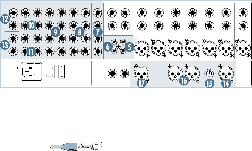
5. TAPE OUT
Use these stereo jacks to capture the entire
performance to tape. The signal at these jacks
is the main mix, post-MAIN INSERTS (13) and
post-MAIN MIX FADER (72). Signals at these
jacks will depend on the levels set by the main
mix fader.
RCA unbalanced wiring:
Tip = hot, sleeve = shield
6. TAPE IN
Patch the outputs of an intermission enter-
tainment device here. Any line level mono or
stereo device can be used: tape, CD player,
television audio, etc. See TAPE RETURN TO
PHONES/C-R (69) and TAPE RETURN TO
MAIN MIX (71) for more information.
When connecting a mono device (just one
cord), use a “Y-splitter” RCA adapter. It turns a
mono cord into two cords; so both the left and
right tape input jacks can be patched. This
adapter is widely available.
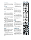
7. SUB INSERTS
With nothing plugged into these jacks, the
subgroup mix goes straight through the SUB-
GROUP FADER (60) to the SUB OUTS (8).
With an effects device plugged into these jacks,
the subgroup mix leaves the mixer, goes
through the effects device and back into the
mixer’s subgroup faders.
Use these jacks to send a subgroup mix
through a compressor, graphic equalizer or
similar device. Since the insert is before the
subgroup faders, moving the fader will not
alter the level sent to a compressor, thereby
preserving the original signal’s characteristics.
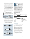
These unbalanced insert jacks are wired ex-
actly the same as shown for INSERT (3) on
page 15.
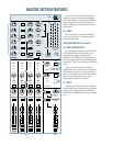
8. SUB OUTS
In live sound applications, these jacks can
be patched into secondary amplifiers, allowing
levels to be controlled, independently of the
main mix, via the SUBGROUP FADERs (60).
Alternatively, the MAIN OUTS (12) (16)
could feed the amplifiers while the subgroups
feed a recorder.
In studio applications, these outputs can be
used as four separate paths to feed four or
more tracks of a multi-track recorder.
See 1-2 & 3-4 (40) and L/R ASSIGN (59) for
more information.
Accepts 1/4” TRS balanced or 1/4” TS unbal-
anced plugs, see page 14 for wiring details.
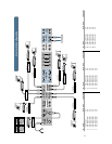
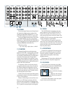
DOUBLE BUSSING
Although this is a “four-buss mixer,” mean-
ing there are four separate subgroups
available, it can be used to feed all eight tracks
of a multi-track recorder, thanks to a trick
called Double Bussing.
SUB OUTS 1 and 5 carry the same signal,
and so do 2 and 6, 3 and 7, 4 and 8. Patch these
outputs into the corresponding inputs of your
multi-track recorder.
To record onto track 1, for example, put
track 1 in record mode, but leave track 5 in
safe mode. To record onto track 5, put track 5
in record and put track 1 in safe mode.
INSERT INSERT INSERT INSERT INSERT INSERT INSERT
MIC 20
TAPE OUTTAPE IN
TALK BACK
MIC
R
R
R
(MONO)
4
L
L
L
3
2
1
L
CONTROL ROOM OUTMAIN INSERTS
3
3
4
2
3
1
1
LL
R
RR
L
24
23 21
22
20
MIC 19
19
LINE IN
(BAL OR UNBAL)
LINE IN
(BAL OR UNBAL)
LINE IN
(BAL OR UNBAL)
LINE IN
(BAL OR UNBAL)
LINE IN
(BAL OR UNBAL)
LINE IN
(BAL OR UNBAL)
LINE IN
(BAL OR UNBAL)
MIC 18
18
MIC 17
17
MIC 16
16
MIC 15
15
MIC 14
14
RIGHT
MAIN OUT
LEFT
MAIN OUT
MONO
MAIN OUT
OUTPUT
LEVEL
PHONES
2
PHONES
1
OFF
POWER
ON
OFF
PHANTOM
ON
MONO MONO
PIN 2 = HOT
PIN 3 = COLD
FUSE INSIDE
CAUTION:
TO REDUCE
THE RISK OF FIRE, REPLACE
WITH THE SAME TYPE FUSE
AND RATING
OO
+6
MAIN
BALANCED
OUTPUTS
R
R
L
L
AUX SENDS
(BAL OR UNBAL)
STEREO AUX RETURNS
(BAL OR UNBAL)
SUB INSERTS
(BAL OR UNBAL)
6
2
5
14
R
R
L
R
L
7
8
6
5
SUB OUTS
(BAL OR UNBAL)
4
2
MAIN OUTS
(BAL OR UNBAL)
(BAL OR UNBAL)
X
D
R
M
I
C
P
R
E
X
D
R
M
I
C
P
R
E
X
D
R
M
I
C
P
R
E
X
D
R
M
I
C
P
R
E
X
D
R
M
I
C
P
R
E
X
D
R
M
I
C
P
R
E
X
D
R
M
I
C
P
R
E
TIPSLEEVETIPSLEEVE