17
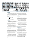
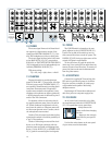
9. STEREO AUX RETURNS
Patch the outputs of external parallel ef-
fects devices (reverb, delay, etc.) to these
inputs.
When connecting a mono device (just one
cord), always use the LEFT (MONO) input and
plug nothing into the RIGHT input. A trick
called “jack normalling” will cause the signal to
appear on both sides.
Accepts 1/4” TRS balanced or 1/4” TS unbal-
anced plugs, see page 14 for wiring details.
10. AUX SENDS
With aux sends in “pre” mode, patch these
jacks into stage monitor amplifier inputs. With
aux sends in “post” mode, patch these jacks
into the inputs of an effects device. See AUX
(26) and PRE (27) for more information.
Accepts 1/4” TRS balanced or 1/4” TS unbal-
anced plugs, see page 14 for wiring details.
11. CONTROL ROOM OUT
These line-level jacks are used to feed am-
plifier inputs in a control room situation,
typically found in a recording studio.
The stereo signal at these jacks is the same
as the MAIN OUTS (12) (16), except when any
SOLO (39) (47) (52) (57) or the TAPE RE-
TURN TO PHONES/C-R (69) is engaged. Its
level is independently controlled by PHONES/
C-R LEVEL (70).
Accepts 1/4” TRS balanced or 1/4” TS unbal-
anced plugs, see page 14 for wiring details.
12. MAIN OUTS (TRS) and
16. MAIN OUT (XLR)
Available in two types, XLR and TRS, the
main output represents the end of the signal
path, just after the MAIN MIX FADER (72),
where the fully mixed stereo signal enters the
real world.
The XLR balanced outputs will add 6dB
when connected to balanced inputs, thereby el-
evating signal from the noise floor by that
amount.
The TRS balanced outputs offer the advan-
tage of having no 6dB level change to deal
with, while still providing extraneous noise re-
jection. These accept 1/4” TRS balanced or 1/4”
TS unbalanced plugs, see page 14 for wiring
details.
13. MAIN INSERTS
With nothing plugged into these jacks, the
main mix goes straight through the MAIN MIX
FADER (72) to the MAIN OUTS (12) (16).
With an effects device plugged into these jacks,
the main mix leaves the mixer, goes through
the effects device and back into the mixer’s
main mix faders.
Use these jacks to send the main mix
through a compressor, graphic equalizer or
similar device. Since the insert is before the
main mix fader, moving the fader will not alter
the level sent to a compressor, thereby preserv-
ing the signal’s characteristics.
These unbalanced insert jacks are wired ex-
actly the same as shown for INSERT (3) on
page 15.
14. MONO MAIN OUT
The signal sent out of this XLR jack is a sum
of the left and right signals at the MAIN OUTS
(12) (16). It can be used to feed a mono sound
system or a mono recording device. See OUT-
PUT LEVEL (15) for more information.
This XLR balanced output will add 6dB
when connected to a balanced input, thereby
elevating signal from the noise floor by that
amount.
Accepts XLR balanced plugs, see page 14.
15. OUTPUT LEVEL
Use this knob to independently set the level
of the MONO MAIN OUT (14). The level is also
dependent on the level set by the MAIN MIX
FADER (72). Unity gain is at 3 o’clock, and
there is 6dB additional gain available when
turned fully up.
To feed a microphone input, like that found
on a camcorder, turn this knob down to the
9:00 range. Use the device’s input meters to as-
sure a good level.
17. TALKBACK MIC
Connect a balanced dynamic microphone to
this XLR jack to utilize the mixer’s talkback
feature (66) (67) (68). This input does not
provide phantom power, so it cannot accept
condenser microphones.
Accepts XLR balanced plugs, see page 14.


