23
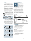
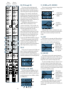
STEREO AUX RETURNS: (48 to 52)
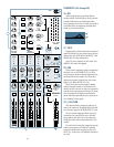
48. STEREO AUX RETURNS
Having entered through the STEREO AUX
RETURNS (9) jacks, effects returns are con-
trolled by these knobs, and typically continue
on to the MAIN MIX FADER (72). Effect re-
turns are the “wet” signals, to be combined
with the channels’ original “dry” signals in the
main mix.
Turned fully up, these controls provide
20 dB of additional gain; the center “U” label is
unity gain and fully down is off. These knobs
are typically set near unity and left alone.
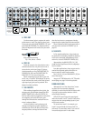
49. TO AUX SEND 1-2
These knobs work just like the channel
strip’s AUX (26) 1 and 2 knobs; but here, the
source signal is the STEREO AUX RETURNS
(9) 1 and 2. Typically, these knobs are used to
add effects to the stage monitors.
Via these knobs, aux return 1 combines its
left and right sides to feed aux send 1; stereo
aux return 2 combines to feed aux send 2.
Turned fully up, these controls provide 15 dB of
additional gain, the center “U” label is unity
gain and fully down is off.
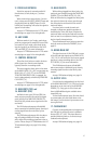
50. ASSIGN TO SUB and 51. SUB
These switches allow stereo aux return 4 to
be sent to pairs of subgroups, instead of being
sent directly to the main mix. Engage ASSIGN
TO SUB (50) to divert aux return 4 to the sub-
groups; use SUB (51) to choose the subgroup
pair, 1-2 (switch up) or 3-4 (switch down).
For live sound, subgroups allow a group of
channel levels (and aux return 4) to be con-
trolled by one or two subgroup faders. For
multi-track recording, subgroups can be used
to route groups of channels (and aux return 4)
to specific tracks of a multi-track recorder.
See L/R ASSIGN (59) and SUBGROUP
FADER (60) for more information.
52. SOLO
Engaging this switch isolates the associated
signal and sends it to the control room, phones
and meters. See RUDE SOLO LIGHT (61) and
MODE (63) for more information.
Note: In PFL mode, aux returns are not
soloed before their master level controls, but
are instead summed after the controls into a
mono signal and sent to the PFL mix.
53. TAPE RETURN
Having entered through the TAPE IN (6)
jacks, tape returns are controlled by these
knobs, and then sent to TAPE RETURN TO
PHONES/C-R (69) and TAPE RETURN TO
MAIN MIX (71).
Turned fully up, this provides 20dB of addi-
tional gain, the center “U” label is unity gain
and fully down is off. These knobs are typically
set near unity and left alone.
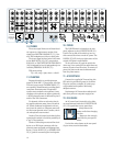
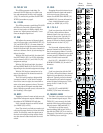
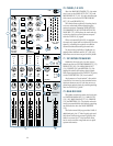
54. METERS
The mixer’s peak metering system is made
up of two columns of thirteen LEDs each, with
thresholds ranging from -40dB up to “CLIP”
(+22dBu at TRS MAIN OUTS (12), +28dBu at
the XLR MAIN OUT (16)).
The meters display the main mix, post
MAIN MIX FADER (72). However, when a
SOLO (39) (47) (52) (57) switch is engaged,
the meters will instead display the solo infor-
mation.
A good mix will show the meter’s peaks
flashing anywhere between -10 and +10dB. Re-
member that most amplifiers clip at about
+10dB, and some recorders aren’t so forgiving
either. For best real-world results, try to keep
your peaks between “0” and “+7.”
ZERO EQUALS ZERO
You may already be fa-
miliar with “+4” and “-10”
operating levels. Basically,
what determines an operat-
ing level, besides available
headroom, is the relative
0dB VU chosen for the meters. A “+4” mixer,
with a +4dBu output signal, will actually dis-
play 0dB on its meters. A “-10” mixer, with a
-10dBV output signal, will also display 0dB.
To eliminate that confusion, Mackie’s com-
pact mixers use a simpler method, where zero
equals zero: 0dBu (0.775V) at the output
shows as 0dB VU on the meters. If a “+4” out-
put is desired, set the mix levels so the meters
“average” at +4dB. If a “-10” output is desired,
set the mix levels so the meters “average” at -
10dB.
55. POWER LED
This LED glows when the POWER (20)
switch is turned on.


