


SCHNEIDER DIGITAL MICROPHONES FOR HIGH RESOLUTION AUDIO
AES 31st International Conference, London, UK, 2007 June 25–27
2
principle to P48 defined in IEC61938 [6], but adapted to
the lower voltage and higher current requirements of
ADC components. It already featured a gain ranging
ADC, to be discussed later, and limited remote control
functions (pre-attenuation) but yielded sub-optimal
noise figures, compared to standard analogue micro-
phones. Another proprietary solution was presented by
Milab [7].
Although the mentioned developments could not fully
compete technically with state-of-the-art analogue
microphones, they were helpful in starting discussions
amongst manufacturers on the future of digitisation in
microphones. It was found that, before presenting
microphones with digital output to a wide public, all
questions of power supply, interfacing, connector types,
remote control etc. should be put into a public standard,
to allow future products to interconnect between
manufacturers. Accordingly, the German DKE 742.6
committee served as a starting basis, then handing over
to an AES standardization committee to publish the
AES 42-2001 standard [8,9], currently revised to the
2006 edition. Almost ten international microphone
manufacturers were actively or passively involved,
guaranteeing a common consensus. First microphones
complying with the new standard were presented in
2001, as a full-feature large diaphragm microphone
[10], later followed by a measurement microphone [11]
and small diaphragm capsule systems [12,13].
In contrast to the professional audio approach, trying to
provide highest possible audio quality, recently other
solutions have been presented, driven by computer
technology, i.e. mainly USB-powered microphones,
with currently in comparison very limited specification
ranges [14].
2 REASONS AND REQUIREMENTS FOR
DIGITAL MICROPHONES
Analogue output condenser microphones are now, 90
years after their invention by E.C. Wente, certainly a
mature technology. In a professional set-up, with
appropriate cabling and limited outside interferences, a
very high dynamic range of up to 130 dB-A can be
transduced [15,16]. To reduce effects of cable length
and interferences on the comparatively small
microphone output signal, preamplifiers are often
located in close proximity to the microphones. In any
case, proper level matching of all analogue components
is necessary to guarantee optimal signal transmission,
allowing for sufficient head-room and foot-room in the
process. On the other hand, digital technology provides
potentially loss-less transmission, once the analogue-to-
digital conversion has taken place. Accordingly, the
interest for microphones with digital output arose when
high quality ADC technology became available,
allowing conversion only minimally affecting micro-
phone specifications.
Some of the requirements on digital microphones [8]
later realized in the AES 42 standard [9] were
- physical layer interface & protocol
compatibility: AES3 protocol with overlaid
phantom power, using 3-pin XLR connectors,
- control information from
the microphone: via
user bits in the AES3 data stream,
- control information to
the microphone: via low
frequent modulation of the phantom power
voltage.
With the chosen interface, loss-less transmission can be
performed over approximately 100 m also with high-
quality “analogue” microphone cable, approximately
300 m with AES3 “digital” cable. This compares well
with typical values for high-quality analogue set-ups.
An essential point in digital technology is proper
synchronization of all audio streams to a reference
clock. In a minimal set-up a receiver can synchronize to
a single microphone, although this would be in contrast
to typical studio procedures, where either the mixing
console, or a dedicated reference clock provide the
clocking reference. But, with multiple digital micro-
phones one needs to either work with sample rate
converters in every channel at the receiver side (AES42
mode1), or preferably synchronize the microphones to
the reference clock (AES42 mode2). High quality
sample rate converters do increase the cost, and even
though in their current embodiments [17,18] they might
not influence the signal much, they will increase
processing time and thus add to the overall latency,
which can become prohibitive in some applications, e.g.
where direct monitoring is called for.
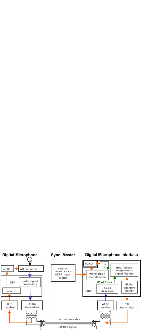
Sending the clock signal directly to the microphone
would imply multi-lead cables, incompatible with
standard 2-wire+ground/return studio wiring. The
solution adopted by AES42, after extensive tests, was to
integrate a voltage controlled crystal oscillator (VCXO)
inside the microphone, yielding an already very stable
data stream but where the frequency is dynamically fine
tuned from the receiver side via the control information
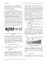
sent to the microphone (Fig. 1).
Figure 1: Connection of a digital microphone, with
synchronization using AES42 interface specification.
Microphone sample rate is controlled (CTL), comparing
extracted microphone rate and external word clock.