


SCHNEIDER DIGITAL MICROPHONES FOR HIGH RESOLUTION AUDIO
AES 31st International Conference, London, UK, 2007 June 25–27
4
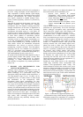
diagram for digital microphones is shown in Fig. 5. The
dynamic range is vastly increased, especially for the
small gain values often used with condenser
microphones, and most importantly becomes
independent of the chosen gain setting. It is now only
limited by the microphone specifications, and by the
digital processing limits, i.e. 0 dBFS level.
Note: The gain shown in Fig. 5 is performed after the
ADC, i.e. in the digital domain.
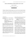
Figure 4: Condenser microphone, with integrated ADC
Figure 5: Dynamic range of a digital microphone
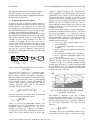
Figure 6: Noise spectra (16k samples, 32x averages) of
an ADC with a. input short-circuited (-140 dBFS-A,
lower curve), b. impedance converter and equivalent
capsule capacitance (-133 dBFS-A, middle curve),
c. impedance converter and real capsule
(-130 dBFS-A, upper curve).
A more detailed perspective of the noise components is
presented in the spectra of Fig. 6. With the input short-
circuited, the ADC shows a roughly white noise
characteristic n
ADC
, typical of today’s Σ∆ –ADCs, with
slightly increasing noise above 20kHz, due to noise
shaping algorithms. Reduced to a single value, the
shown noise is in the region of -140 dBFS-A. The
analogue impedance converter, loaded by a typical
equivalent capsule capacitance, overlays this with a
noise n
ADIn
approx. 7 dB higher, yielding -133 dBFS-A.
Adding a real condenser capsule, the thermal/acoustical
capsule noise n
caps
adds another 3 dB (-130 dB-A). This
means that the thermal/acoustical noise n
caps
of the
capsule and the electrical noise n
ADIn
of the combined
impedance converter and ADC are roughly at the same
level. To achieve even lower values, one would thus
have to work on optimising both electronics and
capsule.
As a side effect, the benign noise of the analogue
components, capsule and impedance converter, with its
largely gaussian distribution serves as an efficient dither
on the ADC quantization noise [19]. With typical
capsule parameters of small and large diameter cond-
enser capsules, the summed noise n
sum,dig
can be at a
level of -122 dBFS or -130 dBFS (A-weighted),
respectively.
4 ADC CHARACTERISTICS
Fig. 6 shows an ADC with dynamic range of 140 dB-A.
ADC circuits matching such a vast dynamic range
would be of the gain ranging type, combining two or
more ADCs working at different signal levels. This is
one realization of a floating point converter, with
exponents of 2
0
and 2
4
[20,21].
Figure 7: Simple gain ranging ADC circuit [10]
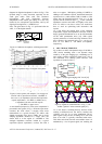
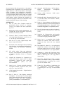
Figure 8: Signals in combined ADCs of Fig. 7, with
audible “glitches” in the summed signal [10]
As is well known, switching directly between ADCs
working at different levels can lead to artefacts like
“glitches” (see Fig. 8), or noise modulation [20,21],
when signal levels pass the switching level. The noise
floor of an ADC is typically wide-band white noise.
This white noise then becomes most audible when it is
modulated by a low frequent signal, not masking the
Microphone ADC
Capsule Impedance
Converter
A
D
0s 0.5ms 1.0ms 1.5ms 2.0ms 2.5ms 3.0ms
Time
V - Path-2)
400mV
0V
-400mV
V
400mV
0V
-400mV
Critical switching
Path-1
Path-1 clipped
Path-2
Very precise signal matching required
to avoid glitches and amplitude errors