


SCHNEIDER DIGITAL MICROPHONES FOR HIGH RESOLUTION AUDIO
AES 31st International Conference, London, UK, 2007 June 25–27
3
The essential requirement then for digital microphones
remains to integrate A-to-D conversion providing
dynamic range and resolution comparable to their high
quality analogue counterparts.
3 DYNAMIC RANGE AND NOISE
In order to be able to compare possible benefits of
analogue and digital microphones, one has to look at the
limiting factors, i.e. the behaviour at very small and
large signal levels, corresponding to the noise floor and
the overload characteristics, as well as the typical signal
resolution, with a medium level signal present.
As mentioned, the typical dynamic range of the output
of a condenser microphone capsule can exceed 130 dB,
with typical maximum levels at a surprisingly high
+10 dBu (2.5 V
RMS
) and microphone self noise at
-120 dBu (A-weighted). In the most noise free of
current studio microphones this corresponds to sound
pressure levels of 7 to 137 dB SPL, covering the needs
of most applications. Only in excessively loud settings
will there be a need to (manually) switch the pre-
attenuation on, shifting the microphone’s dynamic range
to higher levels.
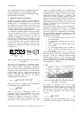
Figure 2: Simple analogue signal chain, with condenser
microphone.
The typical noise voltage n
mic
of a condenser micro-
phone in Fig. 2 roughly follows a pink noise charact-
eristic, whereas dynamic microphones, preamplifiers
and AD converter inputs produce basically white noise.
Preamplifier equivalent input noise n
pre
(EIN) depends
on the amount of gain v chosen. Concentrating all
necessary gain inside the preamplifier, the sum of
analogue equivalent input noise in an analogue
recording chain with ADC will be
2222
,
)( vnvnnn
ADInpremicanasum
++=
. (1)
The physical limit for preamplifier noise is determined
by the thermal noise of the input load R
i
fkTRn
ipre
∆= 4
min,
(2)
with k = 1,38*10-23 J/K (Boltzmann constant), T as
temperature, and ∆f as the bandwidth. For a typical
microphone output impedance of R
i
= 200 Ω, n
R
calculates to -129 dBu (∆f = 23 kHz), or -131.7 dBu-A.
At high gain settings many preamplifiers show noise
figures close to this physical limit, but at low gain
settings n
pre
might be as high as -100…-80 dBu, and is
seldom published in the specifications. One sees that
preamplifier noise is higher or lower than the above
mentioned microphone self noise of -120 dBu-A, and
one main task for the recording engineer is then to
optimise this sum, keeping preamplifier and ADC input
headroom in mind. In analogue set-ups, the rule is to
pull up the gain to studio reference level, trying to avoid
clipping or distortion even with unforeseen very high
sound pressure levels.
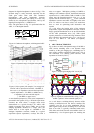
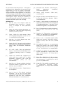
The working dynamic range of a typical microphone /
preamplifier combination is shown in Fig. 3. The output
level of the preamplifier U
out,pre
is shown over gain v.
ADC noise is left out, for simplification, and assuming
that the preamplifier gain will be optimally set, so that
microphone and preamplifier noise dominate. The
limitations are then given by:
o n
200Ω
: -131.7 dBu-A thermal resistive noise as
physical limitation,
o n
pre
: preamplifier equivalent input noise (A-
weighted),
o Max
pre
: maximum preamplifier output level,
here: +20 dBu
o n
mic
: microphone self noise, here: -120 dBu-A
o Max
mic
: maximum microphone output level,
here: +6 dBu
One sees that the preamplifier noise n
pre
reduces the
maximum dynamic range of the microphone Dyn(Mic)
by approx. 16 dB, to a maximum resultant working
dynamic range Dyn(Max) of 110 dB. At the upper/right
axis the diagonal curves of constant equivalent input
sound pressure level are given values, for a microphone
with sensitivity M
0
= 12mV/Pa.
Figure 3: Dynamic range of a combination analogue
microphone / preamplifier
The situation is different in the case of digital
microphones with integrated ADC, as in Fig. 4. The
capsule parameters can be chosen by the designer so
that the capsule output levels are perfectly matched to
the ADC input requirements. The noise sum then
reduces to
22
, ADInmicdigsum
nnn += . (3)
Accordingly, the curve for preamplifier noise in Fig. 3
is replaced by the ADC noise n
ADIn
. The noise over gain
Microphone Preamplifier
A
DC
Capsule Impedance Output
Converter Stage
A
D